Plume neutralizer of space electric thruster

A thruster and space electric technology, applied in the aerospace field, can solve the problems of high equivalent potential of electron current, unsuitable electron source for space electric propulsion system, and contamination of emitter material, so as to improve system efficiency and reliability, avoid Harmful effects, propellant saving effects

Active Publication Date: 2016-06-01
SHANGHAI INST OF SPACE PROPULSION
View PDF5 Cites 23 Cited by
  • Summary
  • Abstract
  • Description
  • Claims
  • Application Information

AI Technical Summary

Problems solved by technology

However, the emission current of products with a lifetime of tens of thousands of hours in a vacuum electron source is generally microampere or milliampere level, and it needs to work in a vacuum degree better than 1×10 -4 In the ultra-high vacuum environment of Pa, products with an emission current of several amperes or tens of amperes require thousands of volts of high voltage and thousands of watts of continuous power supply, and the equivalent potential of the emitted electron current i...

Method used


Image

  • Plume neutralizer of space electric thruster
  • Plume neutralizer of space electric thruster
  • Plume neutralizer of space electric thruster

Examples


Embodiment 1

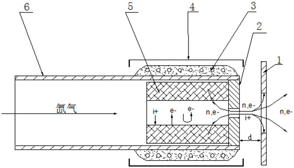
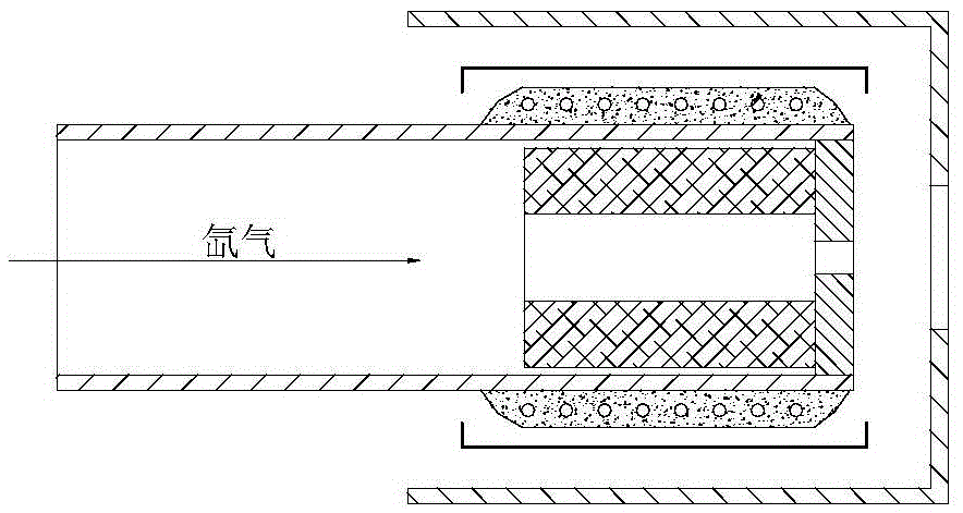
[0022] Such as figure 1 As shown, the neutralizer includes an ignition electrode 1, a top orifice plate 2, a heater 3, a heat shielding cylinder 4, an emitter 5 and a support tube 6, the emitter 5 is installed inside the support tube 6, and the top orifice plate 2 blocks The outside of the emitter 5 is fixedly connected with the support tube 6, the heater 3 is installed on the outside of the support tube 6 at a position corresponding to the emitter 5, the heating zone covers the entire emitter 5, and the heater 3 is wrapped with an insulating ceramic layer; The shielding tube 4 is covered outside the heater 3, and there is a gap between the heater 3 and its insulating ceramic layer to reduce heat conduction and improve radiation protection efficiency. There is a gap between the small holes of the orifice plate 2, the central hole of the ignition electrode 1 is coaxial with the small hole of the top hole plate, the emitter material of the neutralizer is a barium tungsten emitte...

Embodiment 2

[0025] Such as figure 1 As shown, the neutralizer includes an ignition electrode 1, a top orifice plate 2, a heater 3, a heat shielding cylinder 4, an emitter 5 and a support tube 6, the emitter 5 is installed inside the support tube 6, and the top orifice plate 2 blocks The outside of the emitter 5 is fixedly connected with the support tube 6, the heater 3 is installed on the outside of the support tube 6 at a position corresponding to the emitter 5, the heating zone covers the entire emitter 5, and the heater 3 is wrapped with an insulating ceramic layer; The shielding tube 4 is covered outside the heater 3, and there is a gap between the heater 3 and its insulating ceramic layer to reduce heat conduction and improve radiation protection efficiency. A gap is provided between the small holes of the orifice plate 2, and the central hole of the ignition pole 1 is coaxial with the small hole of the top hole plate. The emitter material of the hollow cathode is made of oxide emit...

Embodiment 3

[0028] Such as figure 1 As shown, the neutralizer includes an ignition electrode 1, a top orifice plate 2, a heater 3, a heat shielding cylinder 4, an emitter 5 and a support tube 6, the emitter 5 is installed inside the support tube 6, and the top orifice plate 2 blocks The outside of the emitter 5 is fixedly connected with the support tube 6, the heater 3 is installed on the outside of the support tube 6 at a position corresponding to the emitter 5, the heating zone covers the entire emitter 5, and the heater 3 is wrapped with an insulating ceramic layer; The shielding tube 4 is covered outside the heater 3, and there is a gap between the heater 3 and its insulating ceramic layer to reduce heat conduction and improve radiation protection efficiency. A gap is provided between the small holes of the orifice plate 2, and the central hole of the ignition pole 1 is coaxial with the small hole of the top hole plate. The emitter material of the neutralizer is lanthanum hexaboride ...


PUM


Abstract

The invention discloses a plume neutralizer of a space electric thruster. The neutralizer comprises an ignition electrode, a top hole plate, a heater, a heat shielding cylinder, an emitting body and a support pipe; the emitting body is mounted in the support pipe; the top hole plate shields out of the emitting body, and is fixedly connected with the support pipe; the heater is mounted out of the support pipe opposite to the emitting body; a heating area covers the whole emitting body; the heater is wrapped with an insulation ceramic layer; the heat shielding cylinder covers the heater, and forms gaps with the heater and the insulation ceramic layer; the ignition electrode is mounted at the downstream of the top hole plate, and forms a gap with a small hole of the top hole plate; and a center hole of the ignition electrode is coaxial with the small hole of the top hole plate. The neutralizer generates a lot of electrons through a hot electron ionized gas discharge mode; continuously emitted electrons are high in density; after the gas discharge is stabilized, the self-heating can be performed to maintain discharge, so that the system power consumption is saved; the equivalent potential is low; the effective acceleration voltage of the thruster is higher; and the specific impulse of the thruster is high.

Description

technical field [0001] The invention belongs to the field of aerospace, and in particular relates to a space electric thruster plume neutralizer, which is suitable for plume neutralization of electric thrusters such as Hall, ion, microwave and field emission. Background technique [0002] Compared with chemical propulsion, electric propulsion has a high specific impulse. It can be widely used in missions such as spacecraft orbit transfer, orbit maintenance, attitude control, drag-free control, and main propulsion for deep space exploration. agents, increase spacecraft life, or reduce onboard requirements. With the development of space propulsion technology, electric propulsion has been commercially applied since the 1990s and has been successfully applied to hundreds of spacecraft. Space powers such as the United States, Europe, Russia, and Japan have adopted electric propulsion as a space power competition, deep space The symbolic factor of exploration and commercial appli...

Claims


Application Information

Patent Timeline
IPC IPC(8): F03H1/00
CPCF03H1/0087
Inventor 乔彩霞康小录余水淋唐海辰杭观荣赵震刘冬梅梁爽张岩薛伟华
Owner SHANGHAI INST OF SPACE PROPULSION
Why Eureka
Try Eureka