Hundred nanometer scale ultrafine light needle field focusing

A nanoscale, design method technology, applied in optics, optical components, instruments, etc., can solve the problem that the focused light needle field is on the side of the incident light field, and relies on ultra-precision aspheric processing technology, radial polarization vector beam generation Due to the complex system and high cost of high-end apochromatic microscope objectives, the effect of flexible design method, light structure and low cost is achieved.

Active Publication Date: 2016-06-01
XI AN JIAOTONG UNIV
View PDF4 Cites 11 Cited by
  • Summary
  • Abstract
  • Description
  • Claims
  • Application Information

AI Technical Summary

Problems solved by technology

The modulation method of the refractive optical system is represented by multi-ring pupil filtering, vector beam modulation, and refractive lens focusing proposed by the Singapore Data Storage Research Institute in 2008 (see literature H.Wang, L.Shi, B.Lukyanchuk, C.Sheppard, C.T.Chong.Creationofaneedleoflongitudinallypolarizedlightinvacuumusingbinaryoptics.NaturePhotonics,2008,2:501-505), the research of this kind of method is the most concentrated, the advantage is that the theory is clear, the design is flexible, the disadvantage is that the radially polarized vector beam generation system is complex, and the ring-shaped pupil filter processing Demanding, high-end apochromatic microscope objectives are expensive
The second type of method is based on reflective optical system, which is mainly implemented by annular pupil filtering and parabolic mirror focusing (see liter

Method used


Image

  • Hundred nanometer scale ultrafine light needle field focusing
  • Hundred nanometer scale ultrafine light needle field focusing
  • Hundred nanometer scale ultrafine light needle field focusing

Examples


Embodiment Construction

[0021] The implementation of the present invention will be described in detail below in conjunction with the drawings and examples.

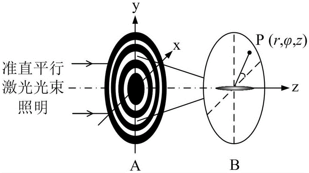
[0022] Such as figure 1 As shown, the short-wavelength ultraviolet laser beam is directly focused by using a microstructured metal film ring plate, and modulated at a distance of tens of microns from the back surface of the ring plate to generate a nanoscale ultra-fine light needle field distribution, which is carried out using Vectorial Angular Spectrum Theory. Light Field Propagation Analysis.

[0023] (1) Integral representation of light field in vector angle spectrum theory

[0024] Assume that linearly polarized light (LPB) vibrating along the X axis propagates forward along the Z axis, such as figure 1 As shown, after diffraction by the microstructured metal film ring plate, at any point in the z>0 vertical axis plane The right-angle component of the electric field E at the position is derived from the vector angle spectrum theory

[...


PUM


Abstract

The invention discloses a hundred nanometer scale ultrafine light needle field focusing design method, belonging to the nanometer photonics focusing and micromachining technology field. The hundred nanometer scale ultrafine light needle field focusing design method comprises steps of using a vector angle theory to integrally describe the diffraction propagation behavior of a rear light field when a polarized light beam illuminates the microstructure metallic film endless belt, using an equivalent numerical value NAeq and a normalization center shielding factor Epsilon to retrain the horizontal scale of the focusing light beam, axially introducing an ultra Gaussian function to restrain to form an ultrafine light needle field and thus to establish a non-linear restrain optimization model, using a configured heredity algorithm and a rapid hankel transformation algorithm to program and solve the optimized model, configuring an optimized initial parameters which comprises a structure parameter and an algorithm parameter to repeatedly execute the optimization algorithm, and optimally choosing the microstructure metallic film endless belt sheet. On the basis of the invention, the metallic film endless belt sheet with different polarized light beams and various scale microstructures and can be used for realizing the micro-nano lithography, the nanometer printing and super-resolution microscopic imaging.

Description

technical field [0001] The invention belongs to the technical field of nano-photonics focusing and micro-processing, and in particular relates to a method for designing ultra-fine light needle field focusing at a hundred nanometer scale. Background technique [0002] Since 2008, the field focusing problem of ultra-fine optical needles has attracted widespread attention from the scientific community, and has become one of the international frontier hot research topics. The ultra-fine optical needle field has important engineering application value, such as in the fields of laser direct writing microlithography, optical data storage, scanning optical nano-microscopy, atomic optics, microscopic particle acceleration, optical manipulation and other fields. [0003] At present, the field focusing modulation methods of ultra-fine light needles are mainly divided into three categories, which are based on refractive optical systems, reflective optical systems and diffractive optical...

Claims


Application Information

Patent Timeline
IPC IPC(8): G02B27/00
CPCG02B27/0012
Inventor 刘涛杨树明王通蒋庄德张国锋
Owner XI AN JIAOTONG UNIV
Why Eureka
Try Eureka