Short-process oily sludge treatment system

A treatment system and a short-flow technology, applied in the field of short-flow sludge treatment systems, can solve the problems of difficult to find pipelines, easy to block pipelines, high cost and operating expenses, etc., to avoid poor operation, avoid sediment deposition, Overcoming the effect of sludge clogging

Active Publication Date: 2016-06-15
RES CENT FOR ECO ENVIRONMENTAL SCI THE CHINESE ACAD OF SCI
View PDF3 Cites 3 Cited by
  • Summary
  • Abstract
  • Description
  • Claims
  • Application Information

AI Technical Summary

Problems solved by technology

In addition to a large amount of aged crude oil, waxy, and colloidal substances, the oil sludge contains a large amount of toxic and harmful substances such as benzene series, phenols, green onions, flowers, polychlorinated biphenyls, and dioxins; in addition, the oil sludge also contains a large number of pathogenic bacteria , parasites, if not treated reasonably and effectively, it will not only waste oil resources, but also cause serious pollution to the environment
[0003] At present, there are various technologies for treating oily sludge, and each method has its own advantages, disadvantages and scope of application. For example, solvent extraction can recover most of the oil resources in oily sludge, but at the same time, there are long processes, complicated processes, and high treatment costs. Disadvantages: The biological treatment method has no secondary pollution, but the treatment period is long; the chemical demulsification method requires additional demulsifiers and heating for heavily emulsified oil sludge, and it is also difficult to treat crude oil; the solid-liquid separation method is suitable

Method used


Image

  • Short-process oily sludge treatment system

Examples


Embodiment Construction

[0019] The technical solutions in the embodiments of the present invention will be clearly and completely described below in conjunction with the accompanying drawings in the embodiments of the present invention. Obviously, the described embodiments are only part of the embodiments of the present invention, not all of them; Based on the embodiments of the present invention, all other embodiments obtained by persons of ordinary skill in the art without making creative efforts belong to the protection scope of the present invention.

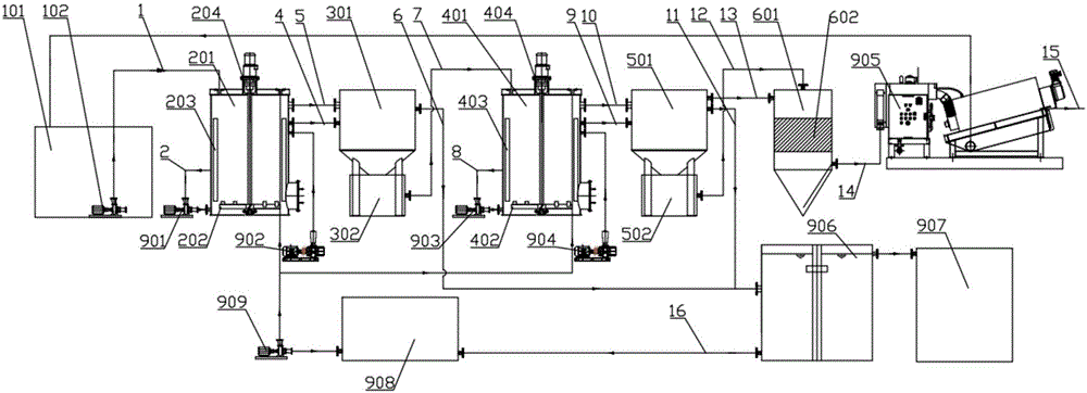
[0020] figure 1 It is a process schematic diagram of the short-flow oil sludge treatment system according to the present invention, wherein each reference numeral is as follows: feed pipeline 1, first backwash pipeline 2, first airlift pipeline 4, first overflow communication pipeline 5. The first oil-water mixture overflow pipeline 6, the first mud-water mixture lifting pipeline 7, the second backwash pipeline 8, the second gas lift pipeline 9, th...


PUM


Abstract

The invention discloses a short-process oily sludge treatment system which comprises a first ultrasonic cleaning device, a first sedimentation device, a second ultrasonic cleaning device, a second sedimentation device, a third sedimentation device, an overlap dewatering machine, a gravitational sedimentation oil separation tank (906), an oil storage tank (907) and a high-temperature water tank. The short-process oily sludge treatment system is characterized in that a tank bottom oily sludge storage pool (101) is used for storing tank bottom oily sludge, to-be-treated materials only can be provided for the short-flow oily sludge treatment system when short-process oily sludge treatment system starting requirements are met by the oily sludge quantity of the tank bottom oily sludge, and double-cam pumps are arranged at the bottom of the tank bottom oily sludge storage pool (101). The short-process oily sludge treatment system has the advantages that the shortcoming of blockage due to oily sludge can be effectively overcome, and the oil and water separation efficiency further can be enhanced; the failure rate of water distribution pipelines can be greatly lowered while basic oily sludge treatment requirements are met.

Description

technical field [0001] The invention belongs to the technical field of environmental protection, and in particular relates to a short-flow sludge treatment system. Background technique [0002] A large amount of black solid and semi-solid waste containing oil will be produced in the process of oil exploitation, gathering and transportation, refining and oily sewage treatment, which is called oil sludge, and its main components are crude oil, mud and water. The size of solid particles in oil sludge can range from less than microns to several inches, most of which are between 1 and 100 microns. The composition of oil depends on the type of crude oil, refinery structure and operating conditions. The composition of sludge may change over time. In addition to a large amount of aged crude oil, waxy, and colloidal substances, the oil sludge contains a large amount of toxic and harmful substances such as benzene series, phenols, green onions, flowers, polychlorinated biphenyls, and ...

Claims


Application Information

Patent Timeline
IPC IPC(8): C02F11/00
CPCC02F11/00
Inventor 高迎新丁然张国林张昱杨敏
Owner RES CENT FOR ECO ENVIRONMENTAL SCI THE CHINESE ACAD OF SCI
Why Eureka
Try Eureka