Pressurization and non-pressurization combined type dual piezoelectric fuel gas injection device

A non-pressurized combined type, injection device technology, applied in the direction of oil supply device, charging system, combustion engine, etc., can solve the problems of size limitation, limited matching engine power, long transmission pipeline, etc., to achieve high power output, Achieve low power output and reduce installation space

Inactive Publication Date: 2016-06-15
西安金中机电工程有限责任公司
View PDF4 Cites 1 Cited by
  • Summary
  • Abstract
  • Description
  • Claims
  • Application Information

AI Technical Summary

Problems solved by technology

[0003] The existing in-cylinder direct injection gas injection devices mostly use a high-pressure pump to compress the gas to a specified pressure, and control the movement of the needle valve through a solenoid valve to realize timing and quantitative control of gas injection, and achieve good energy-saving and emission-reduction effects. : The structure of the high-pressure pump is complex, the transmission pipe from the pump end to the gas injection device is long, and the leakage of supercharged gas is serious; the supercharged gas injection device can meet the requirements of high-pressure or low-pressure injection in a single cycle of gas, but it cannot realize the injection pressure in a single cycle of the engine Variability requirements; the single-nozzle gas injection device matches the limited engine power, and cannot simultaneously meet the engine gas injection control requirements and the gas injection volume requirements under different powers; and although the two gas injection devices can meet the engine gas injection requirements, the size and installation The position is limited by the cylinder head; the precision of gas injection control is high, and the solenoid valve is used to control the movement of the needle valve. Although the timing is controllable, the solenoid valve is affected by the hysteresis circuit and the inductance of the solenoid coil, and the response of the valve core is delayed relative to the control signal. The control accuracy of the gas injection law will be affected; in addition, with the movement of the valve core, the leakage of gas to the solenoid valve end will intensify through the gap between the valve core and the valve body, resulting in a decrease in the gas injection pressure and injection rate, affecting engine power and performance. fuel economy

Method used


Image

  • Pressurization and non-pressurization combined type dual piezoelectric fuel gas injection device
  • Pressurization and non-pressurization combined type dual piezoelectric fuel gas injection device
  • Pressurization and non-pressurization combined type dual piezoelectric fuel gas injection device

Examples


Embodiment Construction

[0020] The present invention will be further described below in conjunction with legend:

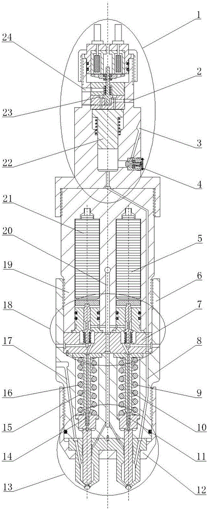
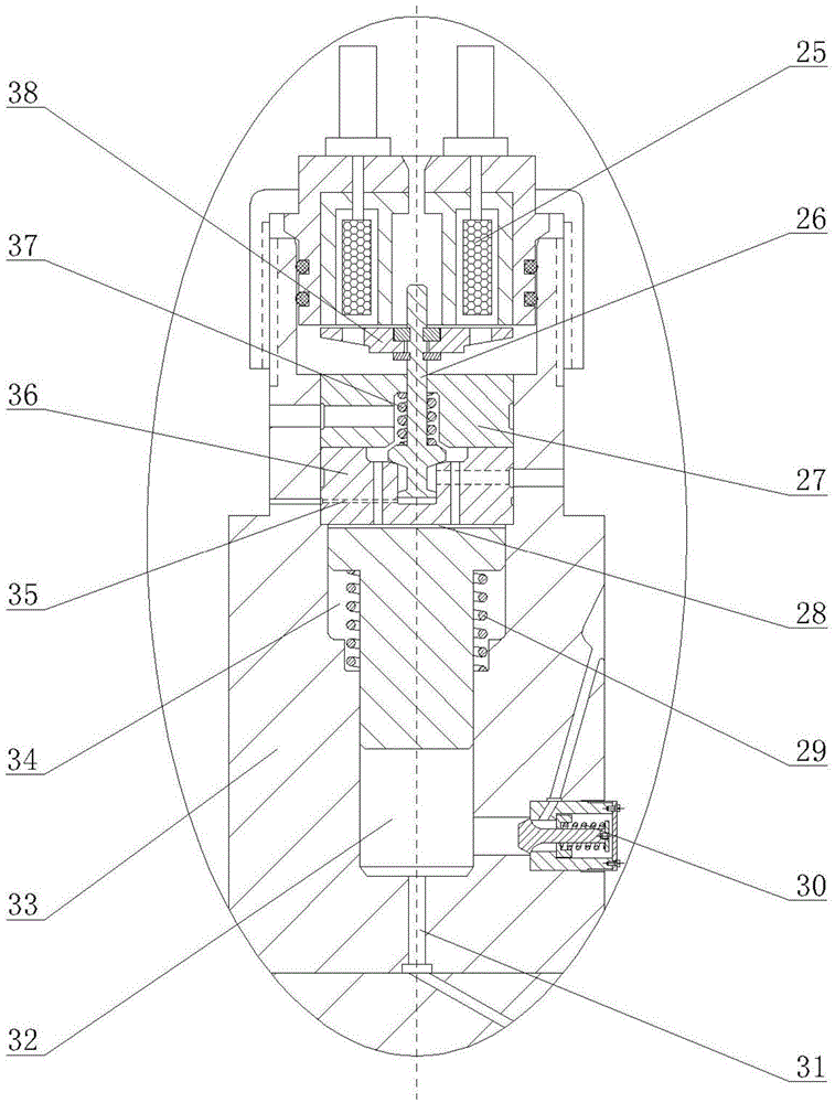
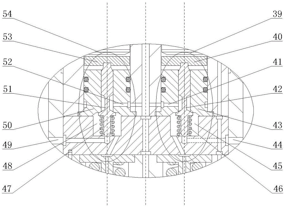
[0021] combine Figure 1-4 , the combined pressurized-non-supercharged dual-piezo electric gas injection device of the present invention mainly includes a gas pressurized part 1, a dual-piezoelectric control part 18, a double gas nozzle part 13, a pressurized device housing 33, a control device housing 19, Injection device housing 6, air intake passage I8, air intake passage II17, pressurized oil inlet oil passage 2, pressurized oil discharge oil passage 24, oil inlet oil passage 20.

[0022]Gas booster part 1 is composed of booster piston 22, booster piston upper cavity 28, booster piston lower cavity 32, booster piston return spring 37, booster piston return spring chamber 34, booster solenoid valve coil 25, booster armature 38. Boost control valve stem 26, boost control valve return spring 29, air inlet 3, boost gas outlet 31, boost control valve oil chamber 23, boost control valve b...


PUM


Abstract

The invention provides a pressurization and non-pressurization combined type dual piezoelectric fuel gas injection device which is formed by combining a fuel gas pressurization device and two piezoelectric control type fuel gas nozzles of the same structure. Pressurized fuel gas of the pressurization device is introduced into one piezoelectric control type fuel gas nozzle, non-pressurized fuel gas is introduced into the other piezoelectric control type fuel gas nozzle, the pressure of fuel gas injected into a combustion chamber can be changed in a single cycle of an engine, and therefore the mixing degree of the fuel gas and air is changed, and the fuel gas combustion characteristic is coordinately controlled. A pressurization electromagnetic valve is used for controlling pressurization of the fuel gas, pressurization of the fuel gas can be controlled in a timed manner, and pressurization injection and non-pressurization injection of the fuel gas can be switched. Two piezoelectric elements are used for controlling injection of two paths of fuel gas, the control precision of the fuel gas injection amount and the control precision of the fuel gas injection rate are high, and injection of a single fuel gas nozzle and injection of the double fuel gas nozzles can be switched fast. Fuel oil is used for sealing the fuel gas, the injection pressure and injection rate of the fuel gas are increased, and the dynamic property and fuel economic characteristic of the engine are improved.

Description

technical field [0001] The invention relates to a dual-fuel engine gas injection device, in particular to a combined supercharging-non-supercharging dual-pressure electric gas injection device. Background technique [0002] The development of alternative fuels for engines is one of the very effective means to solve the problems of energy shortage and environmental pollution. Due to the advantages of abundant resources, low price and clean combustion, gaseous fuel has become an alternative fuel for engines with good development prospects. [0003] The existing in-cylinder direct injection gas injection devices mostly use a high-pressure pump to compress the gas to a specified pressure, and control the movement of the needle valve through a solenoid valve to realize timing and quantitative control of gas injection, and achieve good energy-saving and emission-reduction effects. : The structure of the high-pressure pump is complex, the transmission pipe from the pump end to the...

Claims


Application Information

Patent Timeline
IPC IPC(8): F02M21/02
CPCF02M21/0254F02M21/0257Y02T10/30
Inventor 范立云彭怀利马修真白云董晓露杨立平
Owner 西安金中机电工程有限责任公司
Why Eureka
Try Eureka