A method and a sintering machine for recycling flue gas to form a multi-stage secondary combustion chamber for incinerating solid waste flue gas

A technology of flue gas circulation and sintering machine, which is applied in combustion methods, combustion product treatment, waste heat treatment, etc., can solve the problems of increasing treatment equipment and complex process flow, and achieves the goal of reducing energy consumption, reducing emissions, and reducing dust. Effect

Active Publication Date: 2017-12-08
CHONGQING ANGRUIYUE SCI & TECH
View PDF5 Cites 0 Cited by
  • Summary
  • Abstract
  • Description
  • Claims
  • Application Information

AI Technical Summary

Problems solved by technology

However, they are all aimed at metallurgical sintering flue gas, and part of the flue gas is recycled or treated, so the process flow is more complicated, and additional processing equipment is required
However, the circulation and treatment of sintering flue gas has not been applied in the field of solid waste treatment.

Method used


Image

  • A method and a sintering machine for recycling flue gas to form a multi-stage secondary combustion chamber for incinerating solid waste flue gas

Examples


Embodiment Construction

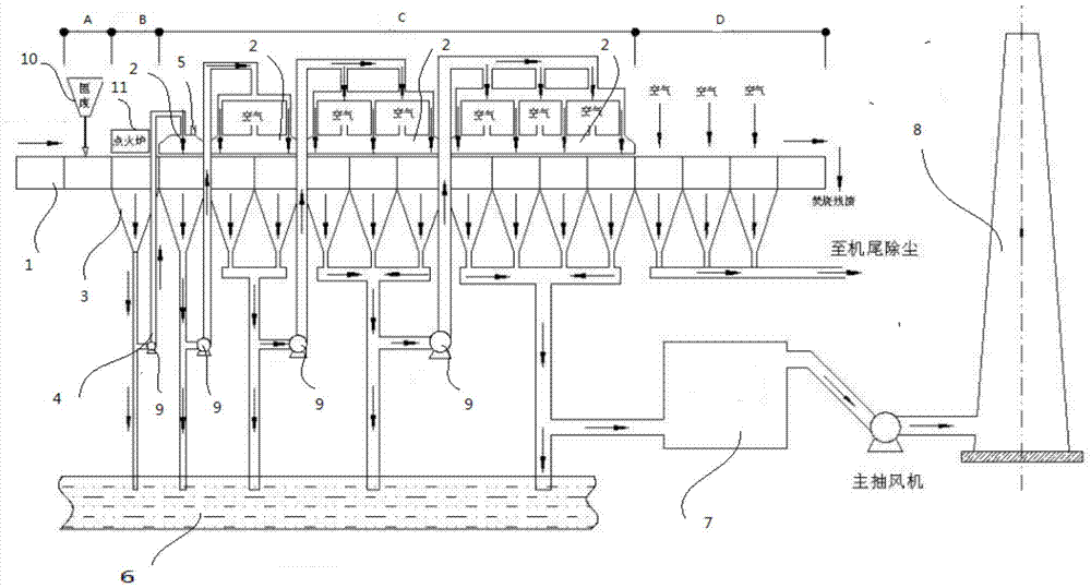
[0027] The present invention utilizes the now mature sintering production equipment, and transforms it on the basis to form such figure 1 The solid waste treatment sintering machine with multi-stage secondary combustion chamber is shown.

[0028] The sintering machine includes a frame, a transmission mechanism, and a trolley. A plurality of trolleys 1 are arranged in series as required, and they run on the frame through the transmission mechanism. The transmission mechanism can be a belt type or a chain type.

[0029] The sintering machine is the same as the traditional one, with a cloth section A at the front end, an ignition section B at the front, an incineration section C at the middle, and a cooling section D at the rear end. A plurality of exhaust hoods 3 are sequentially arranged on the lower frame of the incineration section C, each exhaust hood is connected with a set of negative pressure exhaust pipelines 4, and a fan 9 is arranged on the pipelines.

[0030] In the ...


PUM


Abstract

The invention provides a method for circulating flue gas on a sintering machine to form a multi-stage secondary combustion chamber for incineration disposal of solid waste flue gas. The sintering machine is utilized as main equipment for disposing solid waste, flue gas generated in the incineration process is circularly disposed, and the multi-stage secondary combustion chamber is formed through a next-stage combustion material layer. Specifically, a plurality of independent flue gas hoods are sequentially arranged above an incineration section of the sintering machine, and materials of the incineration section are isolated from external air; each flue gas hood corresponds to one or more draught hoods below the incineration section of the sintering machine, a flue gas inlet is formed in each flue gas hood, and each flue gas inlet is connected with a negative-pressure air draft pipeline of the previous draught hood below the incineration section; all flue gas generated by combustion of the preceding stage is collected to an air inlet position of the next stage to be mixed with distributed fresh air to be used as a combustion gas source of this stage, the flue gas passes through a high-temperature combustion zone in the incineration process to be subjected to secondary combustion, and full-amount circulating combustion of the flue gas is achieved; and combustible substances existing in the flue gas are thoroughly combusted, and the construction investment and operating cost of a flue gas purification system project are reduced.

Description

technical field [0001] The invention belongs to the solid waste incineration treatment technology, and in particular relates to the technology for treating flue gas after general solid waste and hazardous waste are incinerated. Background technique [0002] Solid waste refers to the solid and muddy substances discarded by humans in production and living activities. It is called solid waste, referred to as solid waste, and it also includes solid particles separated from waste water and waste gas. All solid or semi-solid substances that are produced by all human activities and have no use value for the owner and are discarded are collectively referred to as solid waste. Solid waste has a wide range of sources, various types, and complex composition. The hazards of solid waste to the human environment mainly include land occupation, soil pollution, water pollution, air pollution, and environmental sanitation. [0003] Since the composition of solid waste is extremely complex ...

Claims


Application Information

Patent Timeline
Patent Type & Authority Patents(China)
IPC IPC(8): F23G5/16F23J15/02F27D17/00
CPCF23G5/16F23G2202/103F23J15/02F23J2215/10F23J2215/20F23J2215/301F23J2215/40F27D17/001
Inventor 李秉正
Owner CHONGQING ANGRUIYUE SCI & TECH
Why Eureka
Try Eureka