Multi-fluorescence channel detection system for real-time fluorescence quantitative PCR

A real-time fluorescence quantification and fluorescence channel technology, applied in the field of multi-fluorescence channel detection systems, can solve the problems of difficult mechanical structure design and processing of the temperature block, reduce the signal-to-noise ratio of the fluorescence signal, and lengthen the fluorescence detection period, so as to shorten the fluorescence detection period. The effect of cycle time, cost reduction, and easy design and processing

Active Publication Date: 2016-06-15
XIAN TIANLONG SCI & TECH
View PDF7 Cites 19 Cited by
  • Summary
  • Abstract
  • Description
  • Claims
  • Application Information

AI Technical Summary

Problems solved by technology

[0011] 1. Each test tube hole needs 2 optical fibers, and the cost of the optical system is relatively high
[0012] 2. Each test tube hole on the temperature block needs to process 2 holes to insert the optical fiber. When the temperature block has more test tube holes (such as 96 holes), the mechanical structure design and processing of the temperature block are very difficult.
It is difficult to design a temperature block that is small in size and can process so many optical fiber jacks
[0013] 3. If it is expanded to multi-fluorescence channels, twice as many fluorescence excitation and detection units are required to be arranged on the turntable. The volume limitation of the excitation and detection units makes the diameter of the excitation circle and detection circle of the turntable must be increased to accommodate more unit
Then the effective cross-sectional area of ​​the fiber at the excitation end and the emission end becomes half of the existing scheme, and the coupling efficiency of the excitation light and the receiving efficiency of the fluorescence will also decrease by half, res...

Method used


Image

  • Multi-fluorescence channel detection system for real-time fluorescence quantitative PCR
  • Multi-fluorescence channel detection system for real-time fluorescence quantitative PCR
  • Multi-fluorescence channel detection system for real-time fluorescence quantitative PCR

Examples


Embodiment 1

[0073] A multi-fluorescence channel detection system for real-time fluorescence quantitative PCR disclosed in Example 1 of the present invention includes: a temperature block 7, a fluorescence detection unit, an optical fiber disk 15 and a turntable 16, wherein:

[0074] The temperature block 7 is used to accommodate the test sample 6, that is, the test sample 6 is inserted into the temperature block 7, and the bottom of the test sample 6 is equipped with a reaction solution 8. The temperature block 7 of this embodiment will control the temperature of the reaction solution 8 to achieve For PCR cycle, one or more test tube holes are arranged on the temperature block 7 .

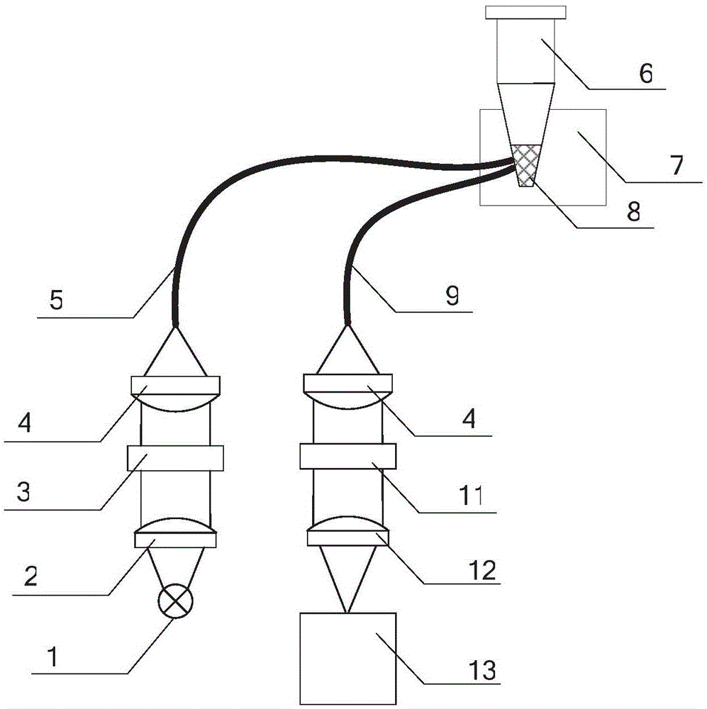
[0075] Fluorescent detection units, such as Figure 6 As shown, including light source 1, collimating lens / collimating lens group 2, excitation filter 3, dichroic mirror 14, fiber coupling lens / fiber coupling lens group 4, optical fiber 17, detection filter 11, converging lens / Converging lens group 12 and p...

Embodiment 2

[0087] When the light source 1 uses some collimated light sources or light sources with small divergence angles, such as high-brightness LEDs. The collimating lens / collimating lens group 2 may not be needed in the fluorescence detection unit, and the collimated light beam emitted by the light source 1 directly enters the excitation filter 3, such as Figure 15 As shown, the fluorescence detection unit in Embodiment 2 includes a light source 1, an excitation filter 3, a dichroic mirror 14, a fiber coupling lens / fiber coupling lens group 4, an optical fiber 17, a detection filter 11, and a converging lens Converging lens group 12 and photoelectric sensor 13 , other structures and principles are the same as those in Embodiment 1, and reference may be made to the specific description in Embodiment 1.

Embodiment 3

[0089] When the photosensor 13 used has a large photosensitive surface and can completely collect the collimated fluorescent light beam output from the fiber coupling lens 4 , the converging lens 12 may not be used. The fluorescent light beam is filtered by the long-pass dichroic mirror and the detection filter 11 and then directly enters the photoelectric sensor. That is, the fluorescence detection unit in Embodiment 3 includes a light source 1, a collimating lens / collimating lens group 2, an excitation filter 3, a dichroic mirror 14, a fiber coupling lens / fiber coupling lens group 4, an optical fiber 17, a detection filter 11 and photosensor 13, such as Figure 16 As shown, other structures and principles are the same as in Embodiment 1.

[0090] Of course, as yet another alternative embodiment, when the light source 1 uses some collimated light sources or light sources with a small divergence angle, and the photosensitive surface of the photoelectric sensor 13 used at the ...


PUM


Abstract

The invention discloses a multi-fluorescence channel detection system for a real-time fluorescence quantitative PCR. The multi-fluorescence channel detection system comprises fluorescence detection units, an optical fiber disc and a turntable, wherein each fluorescence detection unit comprises a light source, an excitation light filter, a dichroscope, optical fiber coupling lenses, optical fibers, a detection light filter and a photoelectric sensor, the dichroscopes enable existing excitation units and detection units to be combined to form a whole, the light emitted by the light source is sequentially subjected to filtration of the excitation light filters and coupling of the optical fiber coupling lenses and finally is emitted into a test tube through the optical fibers to excite the fluorescent substances of samples in the test tubes so as to produce fluorescent light, a part of the fluorescent light returns to the optical fiber coupling lenses through the optical fibers sequentially to be collimated, the detection light filters filter out pure fluorescent light, and the fluorescent light is finally emitted to the photoelectric sensors to perform photoelectric conversion. Multiple optical fibers are inserted into the optical fiber disc, multiple fluorescence detection units are distributed on the turntable, and fluorescence signals of multiple fluorescence channels at multiple test tube hole positions can be sequentially detected through the turntable rotating around the circle center of the optical fiber disc for one circle.

Description

technical field [0001] The invention relates to a real-time fluorescence quantitative PCR detection system, in particular to a multi-fluorescence channel detection system which adopts a fluorescence detection unit combined with an excitation unit and a detection unit for real-time fluorescence quantitative PCR detection. Background technique [0002] In 1996, the AppliedBiosystem company of the United States proposed real-time fluorescent quantitative PCR (real-timeqPCR) on the basis of polymerase chain reaction (Polymerase Chain Reaction, referred to as PCR). In the method, a specific DNA fluorescent probe is added to a PCR reaction system, and the amplification of the target DNA is monitored in real time by collecting the fluorescence intensity of the reaction solution during each temperature cycle. Later, multiplex PCR (MultiplexPCR) was proposed, that is, using the specificity of primers and fluorescent probes binding to target DNA, multiple pairs of primers and multiple...

Claims


Application Information

Patent Timeline
IPC IPC(8): G01N21/64
CPCG01N21/6486
Inventor 李明苗保刚彭年才李政孙尧龚大江
Owner XIAN TIANLONG SCI & TECH
Why Eureka
Try Eureka