
Fin field-effect transistor, fin and fabrication method for fin

A technology of fin field effect and manufacturing method, applied in the field of fins and their manufacture, and fin field effect transistors, can solve the problems of difficult process, high control, high thermal budget, low cost, etc., so as to reduce the manufacturing cost, and the process is simple and easy row effect

Inactive Publication Date: 2016-06-15
INST OF MICROELECTRONICS CHINESE ACAD OF SCI
View PDF5 Cites 0 Cited by
  • Summary
  • Abstract
  • Description
  • Claims
  • Application Information

AI Technical Summary

Problems solved by technology

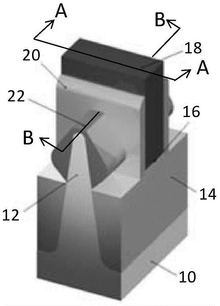
The other is to use bulk silicon substrate 10 to form fins 12, refer to figure 1 As shown, the cost of the bulk silicon substrate is low, but the channel is prone to leakage defects, but it is necessary to form a PTSL (PunchThoughStopLayer, punch through stop layer) under the fin, the process is difficult to control and the thermal budget is high

Method used


Image

  • Fin field-effect transistor, fin and fabrication method for fin
  • Fin field-effect transistor, fin and fabrication method for fin
  • Fin field-effect transistor, fin and fabrication method for fin

Examples


Embodiment Construction

[0034] In order to make the above-mentioned objects, features and advantages of the present invention more obvious and understandable, the specific embodiments of the present invention will be described in detail below with reference to the accompanying drawings.

[0035] In the following description, many specific details are explained in order to fully understand the present invention, but the present invention can also be implemented in other ways different from those described here, and those skilled in the art can do it without departing from the connotation of the present invention. Similar promotion, therefore, the present invention is not limited by the specific embodiments disclosed below.

[0036] Secondly, the present invention will be described in detail in conjunction with schematic diagrams. In detailing the embodiments of the present invention, for ease of description, the cross-sectional view showing the device structure will not be partially enlarged according to th...


PUM


Abstract

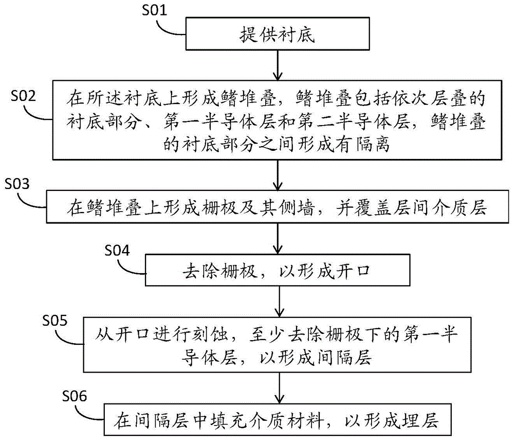
The invention discloses a fabrication method for a fin of a fin field-effect transistor. The fabrication method comprises the following steps of providing a substrate; forming a fin stack on the substrate, wherein the fin stack comprises substrate parts, a first semiconductor layer and a second semiconductor layer which are sequentially laminated, and isolation is formed among the substrate parts of the fin stack; forming a grid and a side wall of the grid on the fin stack, and covering a dielectric layer among layers; removing the grid, and exposing the surface of the fin stack to form an opening; etching from the opening, at least removing the first semiconductor layer under the grid to form a spacing layer; and filling the spacing layer with a dielectric material to form a buried layer. According to the fabrication method, a buried oxide layer is formed in a channel region, and the fin field-effect transistor has the advantage of a device similar to a silicon on insulator (SOI); and meanwhile, the fin height can be controlled according to the thickness of the second semiconductor layer, the demands of different devices are met, and the process is simple and practical.

Description

Technical field [0001] The invention belongs to the field of semiconductor manufacturing, and particularly relates to a fin-type field effect transistor, a fin and a manufacturing method thereof. Background technique [0002] With the high integration of semiconductor devices, the channel length of MOSFET continues to shorten, a series of effects that can be ignored in the MOSFET long channel model become more and more significant, and even become the dominant factor affecting device performance. This phenomenon is collectively referred to as short channel Tao effect. The short channel effect will deteriorate the electrical performance of the device, such as causing problems such as a decrease in gate threshold voltage, an increase in power consumption, and a decrease in signal-to-noise ratio. [0003] In order to overcome the short channel effect, a three-dimensional device structure of fin field effect transistor (Fin-FET) is proposed. Fin-FET is a transistor with a fin-shaped c...

Claims


Application Information

Patent Timeline
Patent Type & Authority Applications(China)
IPC IPC(8): H01L21/336H01L29/78H01L29/06
Inventor 唐兆云徐烨锋唐波王红丽许静李春龙杨萌萌闫江
Owner INST OF MICROELECTRONICS CHINESE ACAD OF SCI
Learn More