Permanent magnet vacuum circuit breaker

A vacuum circuit breaker and permanent magnet technology, applied in high-voltage air circuit breakers, circuits, switchgear and other directions, can solve problems such as failure, device function failure, circuit breaker instability, etc., to ensure the safety of electricity consumption and ensure effective monitoring , to ensure the effect of reliability

Active Publication Date: 2016-06-15
BEST ELECTRICAL
View PDF7 Cites 2 Cited by
  • Summary
  • Abstract
  • Description
  • Claims
  • Application Information

AI Technical Summary

Problems solved by technology

[0009] (2) The pole is an important component of the circuit breaker, and its reliability directly affects the performance of the circuit breaker, and the performance of the current pole needs to be strengthened urgently
[0010] (3) In the circuit breaker and the switch cabinet where it exists, there are many spring devices such as opening springs, extension springs, energy storage springs, etc., and once one of these springs falls off or relaxes, it will make the combination with it The function failure of the device will also cause the instability or failure of the circuit breaker. It can be seen that how to effectively monitor and judge whether the spring is in a normal working state is a problem that cannot be ignored in the use of circuit breakers.
[0011] (4) Many components are assembled in the switchgear. During the factory installation or maintenance and assembly of these components, there is a positioning problem. How to design a simple and efficient positioning aid to make the above-mentioned installation or assembly become handy
[0013] (6) The permanent magnet mechanism controller is the core control unit of the permanent magnet mechanism vacuum circuit breaker. The commonly used permanent magnet mechanism vacuum controller is not highly intelligent, and the line protection and monitoring functions are insufficient. The opening and closing bridge IGBT drive circuit Generally, it is photoelectrically isolated and driven and controlled by a digital signal processor (IGBT is an insulated gate bipolar transistor), while the energy storage capacitor is generally charged through a charging circuit. This design can save costs, but the driving signal is anti-interference and reliable. There are deficiencies in performance, which can easily lead to the unreliable turn-on and turn-off of IGBT units, which directly affects the operating performance of opening and closing.

Method used


Image

  • Permanent magnet vacuum circuit breaker
  • Permanent magnet vacuum circuit breaker
  • Permanent magnet vacuum circuit breaker

Examples


Embodiment 1

[0047] This embodiment mainly introduces a high-voltage circuit breaker. The high-voltage circuit breaker includes a circuit breaker housing, a circuit breaker body, an operating mechanism and a control module.

[0048] Further, the circuit breaker body is a vacuum circuit breaker body.

[0049] Further, the circuit breaker housing is further provided with a metal shield, and the control module is arranged in the metal shield.

[0050] Further, the control module includes an intelligent control circuit module, an arc extinguishing control module, a power supply protection module, and an opening and closing count monitoring switch module.

[0051] Further, the metal shield is provided with a plurality of cooling holes.

Embodiment 2

[0053] This embodiment is carried out on the basis of the foregoing embodiments. It should be specially stated that this embodiment is not only applicable to the content described in this application, but also applicable to other circuit breakers not described in this application, and has strong versatility.

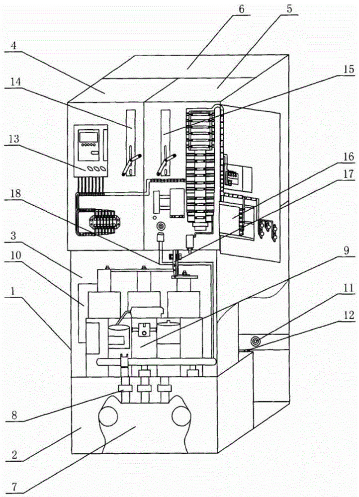
[0054] This embodiment is a combined electrical cabinet, such as image 3 As shown, it includes incoming line cabinet 1, which is subdivided into incoming line room 2, circuit breaker room 3, metering room 4, instrument room 5, and busbar room 6;

[0055] The incoming line room 2 and the circuit breaker room 3 are respectively located in the lower and middle parts of the incoming line cabinet, the metering room 4 and the instrument room 5 are located in front of the upper part of the incoming line cabinet 1, and the busbar room 6 is located in the upper rear of the incoming line cabinet 1;

[0056] A double-winding double-ratio voltage transformer 7 and a high-voltage f...

Embodiment 3

[0065] This embodiment is implemented on the basis of one of the preceding embodiments or on the basis of any combination of two or more embodiments. It should be specially stated that this embodiment is not only applicable to the content described in this application, but also applicable to other circuit breakers not described in this application, and has strong versatility.

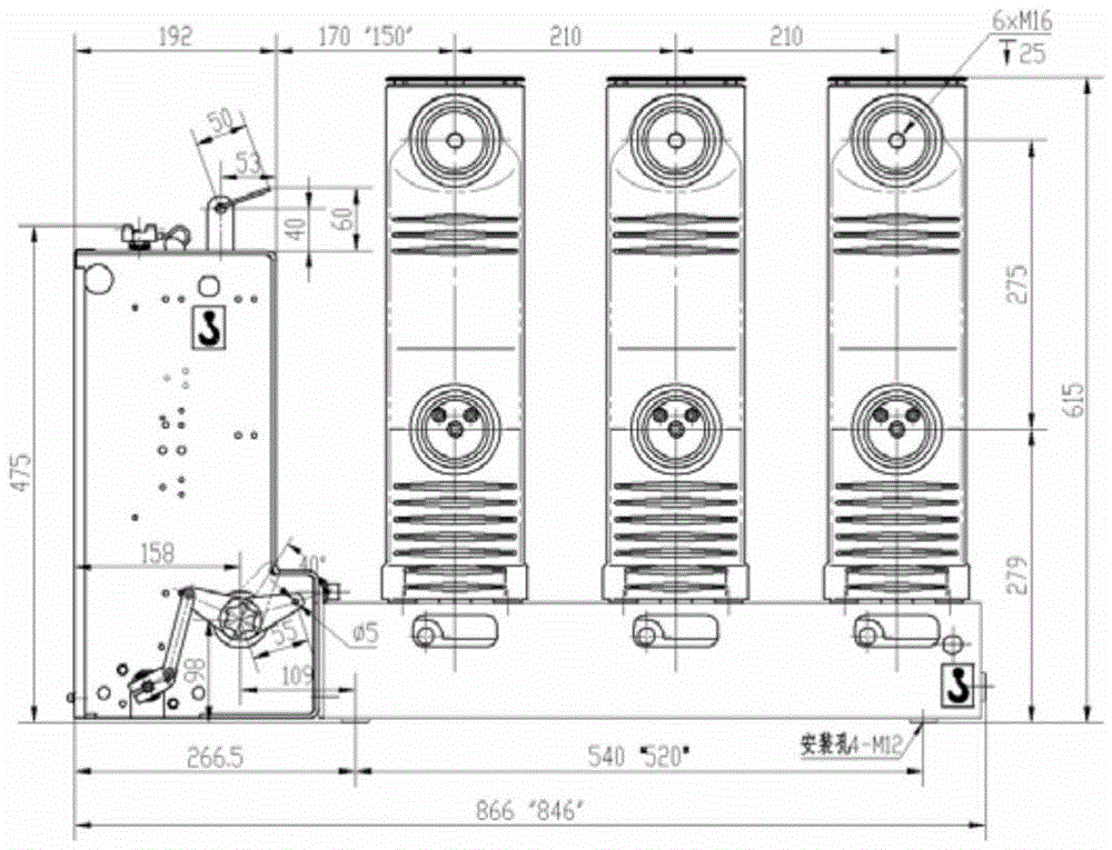
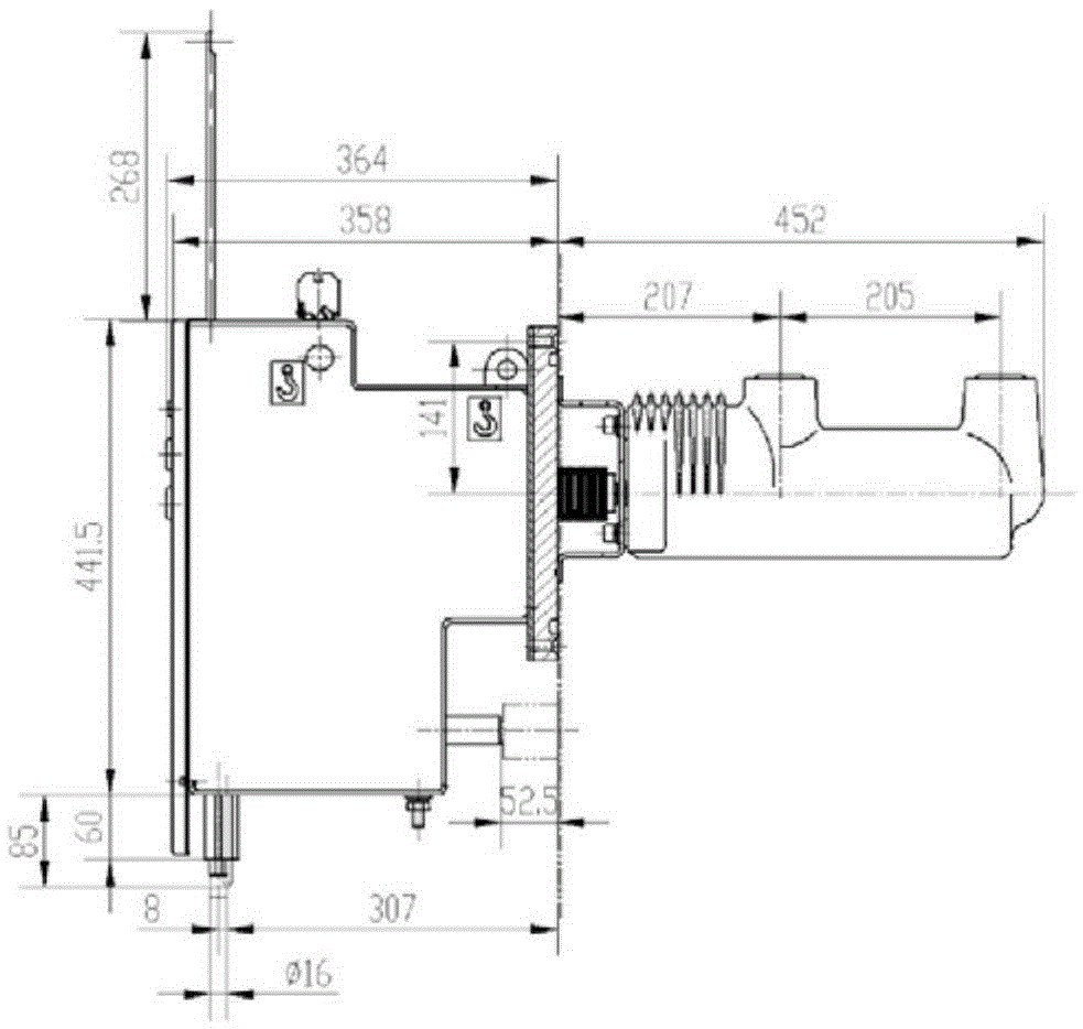
[0066] Such as Figure 4 As shown, a high-voltage vacuum circuit breaker is especially suitable for a fixed gas-filled cabinet, including a box body 19, a circuit breaker operating mechanism 20 is arranged inside the box body 19, and a solid-sealed pole 27 connected to the circuit breaker operating mechanism 20.

[0067] Further, the outside of the box 19 is provided with a mounting plate 24 for mounting the solidified pole, the mounting plate 24 is connected to the fixed inflatable cabinet, and the mounting plate 24 is provided with a mounting hole 23 connected to the fixed inflatable cabinet.

[0068...


PUM


Abstract

The invention discloses a sealed insulating vacuum circuit breaker for an inflating cabinet, and belongs to the field of vacuum high-voltage circuit breakers. The circuit breaker comprises a circuit breaker shell, a circuit breaker body, an operating mechanism and a control module, and also comprises a wire incoming room, a circuit breaker room, a metering room, an instrument room and a busbar room, wherein the wire incoming room and the circuit breaker room are positioned at the lower part and the middle part of a wire incoming cabinet respectively, the metering room and the instrument room are positioned in the front of the upper part of the wire incoming cabinet, and the busbar room is positioned at the back of the upper part of the wire incoming cabinet; a double-winding double-ratio voltage transformer and a high-voltage fuse are mounted in the wire incoming room; a circuit breaker, a three-winding current transformer, a lightning arrester and a sensor are mounted in the circuit breaker room; a loss-voltage timing instrument and a multifunctional metering instrument are mounted in the metering room; an electric energy prepaying device and a protection control device are mounted in the instrument room; and an isolating switch and busbars are mounted in the busbar room. According to the circuit breaker, an auxiliary positioning device and a chassis truck adjusting device are further specially designed, so that the performance of the circuit breaker is superior.

Description

technical field [0001] The invention relates to a circuit breaker, in particular to an indoor fixed side-mounted vacuum high-voltage circuit breaker, which belongs to the field of high-voltage electrical appliances. Background technique [0002] The power system is a large real-time working system. The working mode of the power system has its own characteristics. Its power generation, power transformation, power transmission, and power consumption are completed at the same moment. With the coverage of the power grid system becoming wider and wider, the capacity of power units is getting larger and larger, and the requirements for power supply and consumption are getting higher and higher. Most importantly, the power industry emphasizes safety most, requiring the power system to be able to use Very complete automatic control method to coordinate. [0003] To allow the advanced control system to finally achieve control, it is an important measure to be equipped with a relativ...

Claims


Application Information

Patent Timeline
Patent Type & Authority Applications(China)
IPC IPC(8): H02B13/035H01H33/66
CPCH01H33/66H02B13/035
Inventor 郑慧明钱羽晖夏会法郑晓澜
Owner BEST ELECTRICAL
Why Eureka
Try Eureka