Regenerative multistage heating rotary kiln device

A multi-stage heating and rotary kiln technology, applied in the field of rotary kiln and regenerative multi-stage heating rotary kiln devices, can solve the problems of poor air flow material uniformity, inability to make full use of flue gas waste heat energy consumption resources, etc., to improve production capacity , Improve calcination effect and product quality, reduce the effect of floor space

Active Publication Date: 2016-06-22
SHIJIAZHUANG XINHUA IND FURNACE CO LTD
View PDF7 Cites 7 Cited by
  • Summary
  • Abstract
  • Description
  • Claims
  • Application Information

AI Technical Summary

Problems solved by technology

However, the internal combustion rotary lime kiln is not the above-mentioned large-scale rotary kiln, and cannot make full use of the waste heat of the flue gas, reduce energy consumption and make full use of resources.
The existing rotary kiln cannot be enlarged due to equipment limitations, mainly due to the influence of the airflow and the uniformity of the material after the kiln chamber is enlarged.

Method used


Image

  • Regenerative multistage heating rotary kiln device
  • Regenerative multistage heating rotary kiln device
  • Regenerative multistage heating rotary kiln device

Examples


Embodiment 1

[0030] Invented regenerative multi-stage heating rotary kiln device such as figure 1 As shown, it includes a rotary kiln 11 and a combined preheater. The rotary kiln includes a kiln body, a kiln chamber 28, a kiln head cover 13, a kiln tail cover 12 and a cooler 20. The kiln tail cover is provided with a burner 10, and the kiln head cover is provided with an injection burner 14. The kiln chamber passes through the kiln head cover. Connect to cooler. The combined preheater 24 includes a feed inlet 1 , a smoke exhaust pipe 2 , a preheating chamber 3 , a heat collecting pipe 4 , a heating chamber 17 and a collecting hopper 9 . The feed inlet and exhaust pipe are located on the upper part of the preheating chamber, the heat collecting pipe is located on the lower part of the preheating chamber, and the preheating chamber is connected with the heating chamber through the feeding pipe 5, such as Figure 5As shown, the heating chamber is divided into a preheating section 18 and a p...

Embodiment 2

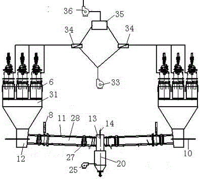
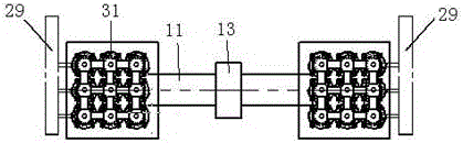
[0033] Another embodiment of the present invention is as figure 2 As shown, it includes a rotary kiln 11 and a Maerz type preheater 31 . The rotary kiln includes a kiln body, a kiln chamber 28, a kiln head cover 13, a kiln tail cover 13 and a cooler 20. The kiln tail cover is provided with a burner 10, the kiln head cover is provided with an ejector burner 14, and the kiln chamber passes through the kiln tail cover. Connect with cooler 5. The Maerz type preheater 31 includes a feed inlet 1, a cylinder body, a plug-in burner 6 and a connecting channel 30, and the kiln body is connected to the kiln chamber of the rotary kiln through the connecting channel and the kiln tail cover 12. The rotary kiln is a rotary kiln with a partition wall. The rotary kiln with a partition wall is composed of an inner ring and an outer ring installed coaxially. The center of the inner ring is the kiln chamber. There is an annular material chamber between the inner ring and the outer ring. . The...

Embodiment 3

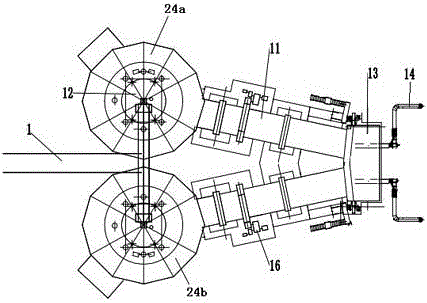
[0035] The third way of the present invention is as image 3 As shown, it includes two rotary kilns 11 and two combined preheaters 24. The two rotary kilns are symmetrically arranged up and down, and are respectively located above and below the kiln tail cover. The kiln chambers of the two rotary kilns are connected through the kiln head cover 13. The kiln tail cover is provided with two injection burners 14, which are respectively inserted into the upper and lower rotary kilns. The two rotary kilns operate alternately, and the two combined preheaters alternately carry out heat storage and heating. When No. 1 combined preheater 24a is heating, the plug-in burner in the combustion chamber burns and heats the material, and the burner and the lower part of the upper rotary kiln The ejector burner of the rotary kiln burns. The flue gas passes through the upper rotary kiln, kiln tail cover, lower rotary kiln and No. 2 combined preheater 24b, and then is discharged through the exha...


PUM


Abstract

The invention relates to a regenerative multistage heating rotary kiln device. The regenerative multistage heating rotary kiln device comprises rotary kilns and raw material pre-heaters. Each rotary kiln comprises a kiln body, a kiln chamber, a kiln head cover, a kiln tail cover and a cooler. Each kiln tail cover is provided with a burner. Each kiln head cover is provided with an ejecting burner body. The raw material pre-heaters are connected with the kiln chambers through the kiln tail covers. The kiln chambers are connected with the coolers through the kiln head covers. The rotary kiln device is provided with 1-50 sets of rotary kilns and the raw material pre-heaters, each set comprises one rotary kiln and 1-50 raw material pre-heaters, and the raw material pre-heaters are combination pre-heaters, Maerz pre-heaters, brettis vertical kiln type pre-heaters or regenerators. According to the regenerative multistage heating rotary kiln device, by combining the rotary kilns with the raw material pre-heaters, the calcination effect and the product quality are improved, energy consumption of lime production is reduced, the production capacity of the device is improved, and occupied areas are decreased advantageously.

Description

technical field [0001] The invention belongs to the technical field of chemical material production equipment, and relates to a rotary kiln, in particular to a regenerative multi-stage heating rotary kiln device. Background technique [0002] Rotary kiln refers to rotary calcining kiln, which belongs to building materials production equipment. Rotary kiln can be divided into cement kiln, metallurgical chemical kiln and lime kiln according to different materials. Cement kilns are mainly used for calcining cement clinker, which can be divided into two categories: dry production cement kiln and wet production cement kiln. Metallurgical and chemical kilns are mainly used for magnetization and roasting of lean iron ore in iron and steel plants in the metallurgical industry. Lime rotary kiln is a widely used kiln for calcining small particle materials. It is suitable for steel, calcium carbide and non-ferrous metal production enterprises. It can directly calcinate 10-40mm fine-g...

Claims


Application Information

Patent Timeline
Patent Type & Authority Applications(China)
IPC IPC(8): F27B7/10F27B7/34F27B7/32F27B7/38F27D17/00C04B2/10
CPCC04B2/10F27B7/10F27B7/3205F27B7/34F27B7/38F27D17/004F27D2017/007Y02P40/40
Inventor 贾会平
Owner SHIJIAZHUANG XINHUA IND FURNACE CO LTD
Why Eureka
Try Eureka