A waste gas heat energy recovery heat exchanger

A heat recovery and heat exchanger technology, which is applied in waste heat treatment, energy industry, climate sustainability, etc., can solve problems such as low heat recovery efficiency, low heat exchange efficiency, and small melting ratio, and achieve high heat recovery efficiency, The effect of increasing the heat exchange area and improving the heat recovery efficiency

Active Publication Date: 2017-08-25
黄志祥 +1
View PDF6 Cites 0 Cited by
  • Summary
  • Abstract
  • Description
  • Claims
  • Application Information

AI Technical Summary

Problems solved by technology

The existing heat exchange chambers are divided into vertical and horizontal types. The horizontal heat exchangers are basically eliminated due to low heat recovery efficiency, easy air leakage and easy blockage, while the cooling chambers in the existing vertical heat exchange chambers The air channel is formed by simply stacking a single box brick in the vertical direction. In order to ensure instant heat exchange efficiency, the brick wall of the box brick should not be too thick, so the load-bearing strength of this box brick is limited, which limits the height of the cold air channel. As a result, the ability of the airflow to evenly surround the cylinder body is poor, the melting ratio is small, and the overall heat transfer efficiency is low, resulting in high energy consumption

Method used


Image

  • A waste gas heat energy recovery heat exchanger
  • A waste gas heat energy recovery heat exchanger
  • A waste gas heat energy recovery heat exchanger

Examples


Embodiment Construction

[0041] The technical solutions in the present invention will be further described below in conjunction with the accompanying drawings and embodiments.

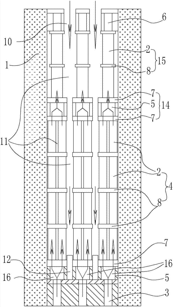
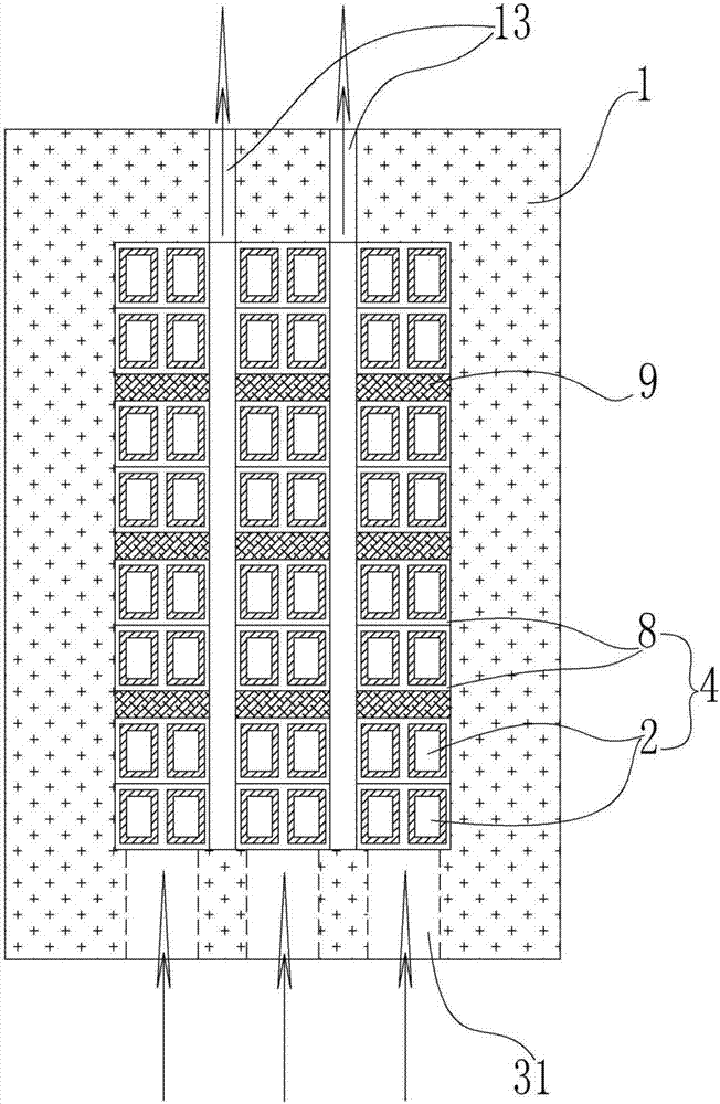
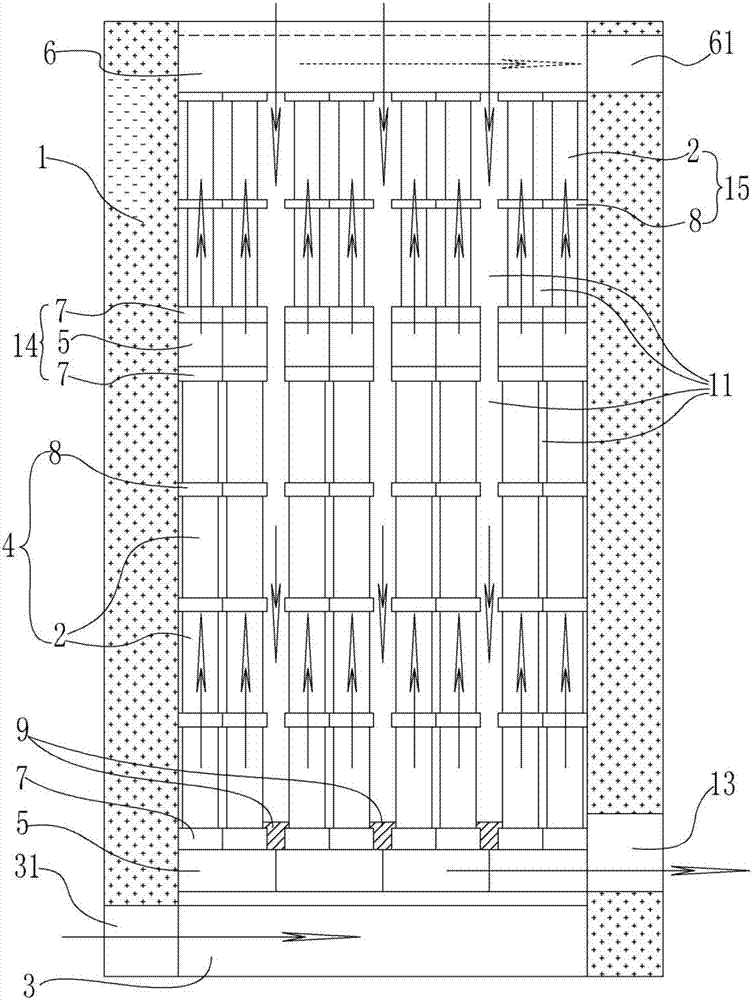
[0042] Such as Figure 1 ~ Figure 3 As shown, the present invention proposes a waste gas heat energy recovery heat exchanger, which includes an inner cavity surrounded by an outer wall 1 and an outer wall 1, and the inner cavity is provided with an air channel and an exhaust gas channel, wherein:

[0043] The air passage includes an injection chamber 3, a distribution chamber 16, a conduction chamber 4, a converging structure 14, a convection chamber 15 and a discharge chamber 6, wherein: the injection chamber 3 is arranged at the bottom of the inner cavity, and the injection chamber 3 has a the entrance 31 at the lower part of the outer wall 1;

[0044] The distribution chamber 16 is arranged above the injection chamber 3 and communicates with it. There are several distribution chambers 16 arranged parallel to each other in ...


PUM


Abstract

The invention provides a waste gas heat energy recovery heat exchanger which comprises an outer wall and an inner cavity. An air channel and a waste gas channel are arranged in the inner cavity. The air channel comprises an injection chamber, distribution chambers, conduction chambers, convergence structures, convection chambers and discharging chambers. Each distribution chamber is formed by sequentially connecting a plurality of variable bonders in the horizontal direction, wherein the variable bonders are provided with inner holes with funnel-shaped longitudinal sections. A clearance is arranged between every two adjacent distribution chambers. The conduction chambers are connected to the upper portions of the distribution chambers through on-single bonders. The conduction chambers are formed by stacking tubular bricks, wherein every four tubular bricks form a group. The top ends of the conduction chambers are connected with the convection chambers through the convergence structures, the convergence structures comprise on-single bonders and variable bonders with large openings of inner holes being downward, and the convection chambers are formed by stacking tubular bricks, wherein every two tubular bricks form a group. The discharging chambers are arranged at the top ends of the convection chambers. The waste gas channel comprises waste gas inlet chambers, waste gas distribution chambers and waste gas converging chambers. According to the waste gas heat energy recovery heat exchanger, three kinds of heat transfer manners are fully utilized for heat exchange, and the heat recovery efficiency is greatly improved; and the height of tubes is reduced, and the building and maintaining cost is remarkably reduced.

Description

technical field [0001] The invention relates to the field of kiln waste heat utilization, in particular to a heat exchanger for recycling the heat energy of kiln waste gas. Background technique [0002] The flue gas discharged from the glass kiln contains a large amount of waste heat. If it is discharged directly without further use, it will inevitably cause a great waste of energy. If the high-temperature exhaust gas discharged from the kiln is used It can realize the recovery and utilization of the waste heat of the exhaust gas, thereby greatly saving energy costs. [0003] The existing kiln heat exchange technology mainly adopts two technologies of regenerator and heat exchange chamber. The regenerator generally arranges and distributes refractory bricks in the inner chamber to form lattice bodies and lattice holes. The contact surface area, when working, first inject the high-temperature exhaust gas generated by the kiln into the grid holes, the exhaust gas heats the gr...

Claims


Application Information

Patent Timeline
Patent Type & Authority Patents(China)
IPC IPC(8): F27D17/00
CPCF27D17/004F27M2001/07Y02P80/15
Inventor 黄志祥黄诚
Owner 黄志祥
Why Eureka
Try Eureka