
Surface treatment milling machine tool

A surface treatment and milling technology, which is applied in the direction of milling machine equipment, milling machine equipment details, metal processing equipment, etc., can solve the problems of incomplete release of stress, vibration, noise, high cost, etc., to improve flexibility, reduce volume, and improve repair efficiency Effect

Inactive Publication Date: 2016-06-29
董博良
View PDF0 Cites 3 Cited by
  • Summary
  • Abstract
  • Description
  • Claims
  • Application Information

AI Technical Summary

Problems solved by technology

[0002] Large-scale mechanical equipment such as rotary kilns and roller mills used in mining, metallurgy, building materials and other industries now often have irregular deformation or wear during operation, such as plane deformation of the base, wear of the outer circle of the rotary parts, etc. , or the stress in the manufacturing process is not completely released, and the aging effect is not fully in place. When transported to the site for installation, the release of the stress will cause the machine to deform. These irregular deformation or wear will cause the equipment to appear during operation. Vibration, noise and other abnormal phenomena pose a threat to the safe and stable operation of the equipment
Therefore, it is very necessary to solve the wear problem in a timely manner. The current method is to dismantle the deformed or worn equipment such as the rotary kiln tire as a whole, and transport it to the manufacturing plant for processing. This is costly and long-term, which affects production.

Method used


Image

  • Surface treatment milling machine tool

Examples


Embodiment 1

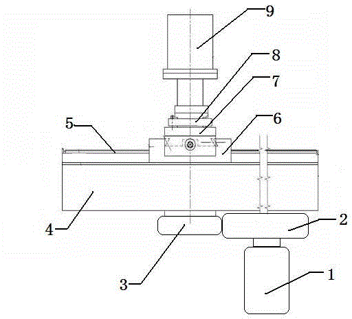
[0012] This embodiment provides a surface treatment milling machine tool, characterized in that: the surface treatment milling machine tool includes a drive motor (1), a first gear (2), a second gear (3), a sliding table (4), Slideway (5), slider (6), milling cutter installation connection (7), tool holder (8), milling power system (9);

[0013] Among them: the sliding table (4) is connected with the slider (6) on the upper side in a sliding connection, the other end of the sliding table (4) is provided with a feed drive motor (1), and the power output shaft of the driving motor (1) Connected to the first gear (2), the first gear (2) is in circumscribed meshing transmission with the second gear (3), and the transmission shaft of the second gear (3) passes through the slide table (4) and is fixedly connected to the slider (6 ), a milling cutter installation connection (7) is installed above the slider (6), and a tool holder (8) and a milling power system (9) are installed throu...


PUM


Abstract

The invention provides a surface treatment milling machine tool. The surface treatment milling machine tool is characterized by comprising a driving motor, a first gear, a second gear, a sliding base, a slideway, a slide block, a milling cutter mounting joint, a knife rest and a milling power system, wherein the sliding base is connected with the slide block located at an upper side in a sliding connection manner, the other end of the sliding base is connected with a feed driving motor, the power-output shaft of the driving motor is connected with the first gear, the first gear is connected with the second gear in an externally-tangent mesh transmission manner, a transmission shaft of the second gear passes through the sliding base and is in fixed connection with the slide block, the milling cutter mounting joint is mounted above the slide block, and the knife rest and the milling power system are installed through the milling cutter mounting joint. The surface treatment milling machine tool has the advantages that surface repair of large mechanical equipment is realized without dismounting of key parts of the large mechanical equipment, so on-line repair of the large mechanical equipment is realized and repair efficiency is improved; the feed driving motor and a cutting power unit employ a hydraulic motor or servo motor, so the problem of heavy weight of a reduction box due to usage of a multi-stage reduction box for speed regulation in the prior art is avoided; and the size of the surface treatment milling machine tool is reduced and flexibility in usage is improved.

Description

technical field [0001] The invention relates to the technical field of on-line processing and repairing of equipment, in particular to a multifunctional on-line processing and repairing device for the surface of large-scale mechanical equipment, and particularly provides a surface treatment milling machine tool. Background technique [0002] Large-scale mechanical equipment such as rotary kilns and roller mills used in mining, metallurgy, building materials and other industries now often have irregular deformation or wear during operation, such as plane deformation of the base, wear of the outer circle of the rotary parts, etc. , or the stress in the manufacturing process is not completely released, and the aging effect is not fully in place. When transported to the site for installation, the release of the stress will cause the machine to deform. These irregular deformation or wear will cause the equipment to appear during operation. Abnormal phenomena such as vibration and...

Claims


Application Information

Patent Timeline
IPC IPC(8): B23C3/00
Inventor 董博良
Owner 董博良
Learn More