
Laser cutting system

A laser cutting and cutting system technology, which is applied in laser welding equipment, welding equipment, metal processing equipment, etc., can solve problems such as difficult detection and control, non-metallic materials cannot be used for capacitor height controllers, and small capacitors, etc., to achieve optimal processing High efficiency, guaranteed laser processing effect, and stable processing quality

Active Publication Date: 2016-06-29
HANS LASER TECH IND GRP CO LTD
View PDF6 Cites 8 Cited by
  • Summary
  • Abstract
  • Description
  • Claims
  • Application Information

AI Technical Summary

Problems solved by technology

However, the use of the capacitor height controller can only work when cutting metal. When the capacitor height controller is cutting non-metal, because the capacitance formed is very small, it is difficult to detect and control, so the capacitor height controller cannot be used for non-metallic materials.

Method used


Image

  • Laser cutting system
  • Laser cutting system
  • Laser cutting system

Examples


Embodiment Construction

[0035] In order to facilitate the understanding of the present invention, the present invention will be described more fully below with reference to the associated drawings. Preferred embodiments of the invention are shown in the accompanying drawings. However, the present invention can be embodied in many different forms and is not limited to the embodiments described herein. On the contrary, these embodiments are provided to make the understanding of the disclosure of the present invention more thorough and comprehensive.

[0036] Unless otherwise defined, all technical and scientific terms used herein have the same meaning as commonly understood by one of ordinary skill in the technical field of the invention. The terms used herein in the description of the present invention are for the purpose of describing specific embodiments only, and are not intended to limit the present invention.

[0037] refer to figure 1 As shown, a laser cutting system provided by the present i...


PUM


Abstract

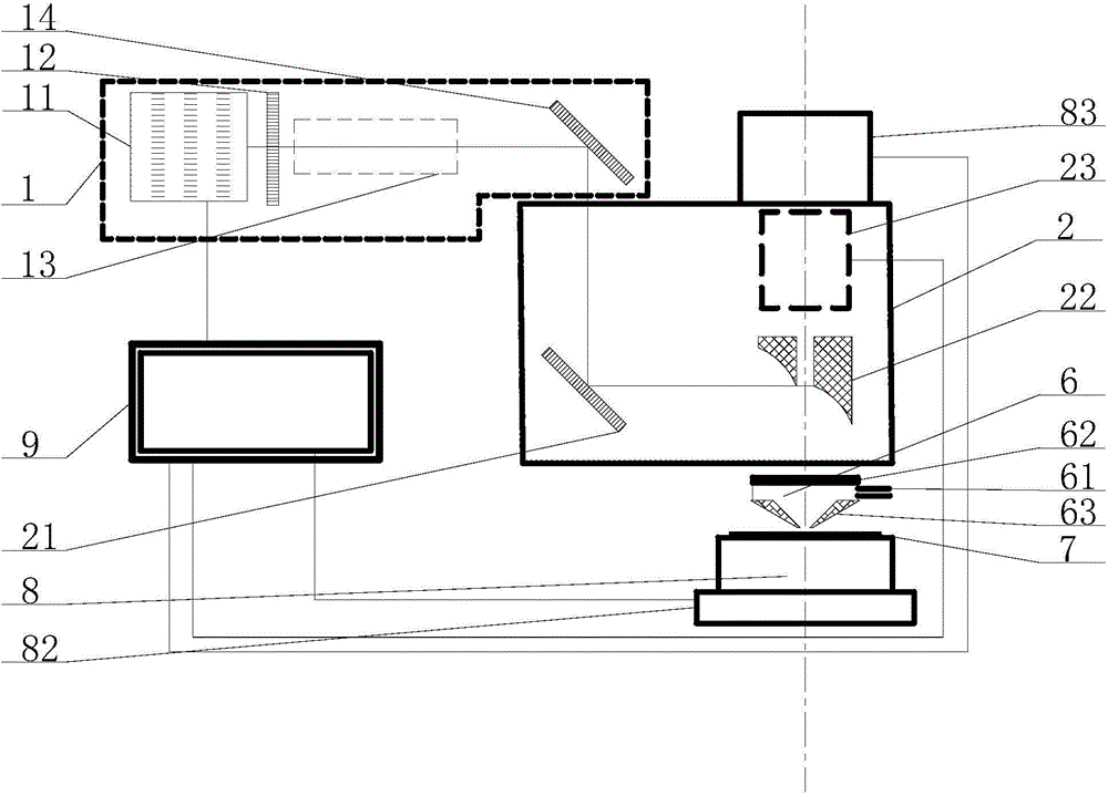
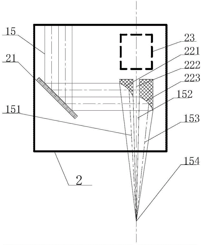
The invention relates to the technical field of laser cutting and discloses a laser cutting system. The laser cutting system comprises a laser light source assembly, an optical assembly, a three-dimensional motion assembly and a computer, wherein the three-dimensional motion assembly comprises an x-y-axis moving platform and a z-axis moving platform, the x-y-axis moving platform drives materials to be machined to move in the x direction and in the y direction, and the z-axis moving platform drives the optical assembly to move in the z direction. The laser light source assembly emits machining laser beams, second laser beams and third laser beams are formed by the machining laser beams under the action of the optical assembly and are focused on the materials to be machined to machine the materials. A first zone without laser beams is formed between the second machining beams and the third machining beams. The computer is connected with the laser light source assembly, the optical assembly, the x-y-axis moving platform and the z-axis moving platform. According to the laser cutting system, images of the surfaces of the materials to be machined can be observed and detected, and focuses of the machining light beams can be automatically adjusted.

Description

technical field [0001] The present invention relates to the technical field of laser cutting, and more specifically relates to a laser cutting system. Background technique [0002] Due to its advantages of high brightness, high directivity, high monochromaticity and high coherence, laser has been widely used in scientific research, national defense, industry and other important aspects of national production. In the industrial field, laser processing, as an advanced manufacturing technology, has the advantages of high efficiency, high precision, high quality, wide range, energy saving and environmental protection, and can realize flexible processing and ultra-fine processing. It is used in automobiles, electronic circuits, electrical appliances, aerospace, iron and steel metallurgy , machinery manufacturing and other fields have been widely used, and have reached a higher level in some industries (such as automobiles, electronics industries, etc.). It plays an increasingly ...

Claims


Application Information

Patent Timeline
Patent Type & Authority Applications(China)
IPC IPC(8): B23K26/38B23K26/064B23K26/046B23K26/14
Inventor 赵建涛肖磊杨锦彬宁艳华高云峰
Owner HANS LASER TECH IND GRP CO LTD
Learn More