
Novel stacked screw sludge dewatering machine and spiral shaft thereof

A sludge dewatering machine, screw shaft technology, applied in water/sludge/sewage treatment, sludge treatment, dewatering/drying/concentrated sludge treatment, etc. The effect of improving, improving the service life, expanding the processing capacity and adapting range

Active Publication Date: 2016-06-29
SHANGHAI TECHASE ENVIRONMENT PROTECTION
View PDF5 Cites 8 Cited by
  • Summary
  • Abstract
  • Description
  • Claims
  • Application Information

AI Technical Summary

Problems solved by technology

[0004] The purpose of the present invention is to overcome the defects of existing conventional dehydration equipment when dealing with large specificity, poor fluidity, high viscosity, and easy to agglomerate mud, and provide a kind of processing capacity and expansion of adaptability, which can handle large specificity, poor fluidity, high viscosity , easy to agglomerate mud, a new type of screw-type sludge dewatering machine and its screw shaft that can improve the service life of the movable ring

Method used


Image

  • Novel stacked screw sludge dewatering machine and spiral shaft thereof
  • Novel stacked screw sludge dewatering machine and spiral shaft thereof
  • Novel stacked screw sludge dewatering machine and spiral shaft thereof

Examples


Embodiment

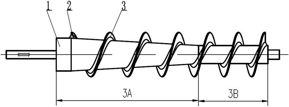
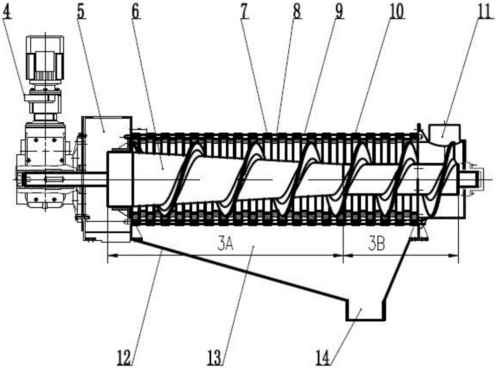
[0022] Such as figure 1 As shown, the screw shaft of a new screw-stacked sludge dewatering machine (referred to as the new screw shaft) adopts a variable-diameter and variable-pitch screw shaft. The mud inlet box gradually becomes smaller, and the lead angle gradually decreases from 16° to 22° to 6° to 14°; the pitch of the shaft body gradually increases along the direction of the mud box, and the pitch is more reasonable; and the screw shaft body is from From the position of 1 / 3 of the shaft length, its diameter gradually increases from the mud inlet box to the mud outlet box. On both sides of the bottom of the helical blade 3 of the novel helical shaft, there are anti-blocking plates 2 with an included angle of 20° to 45° with the center line of the shaft body 1, and the height is not less than 2 / 3 of the height of the helical blade. The function of the blocking plate is to reduce the frictional resistance of the right angle of the helical blade to the material during the m...


PUM

PropertyMeasurementUnit
thicknessaaaaaaaaaa
surface roughnessaaaaaaaaaa
angleaaaaaaaaaa

Abstract

The invention discloses a novel stacked screw sludge dewatering machine and a spiral shaft thereof. The lead angle arrangement order of spiral blades of the novel spiral shaft is that the lead angle gradually becomes smaller from a sludge discharge box to a sludge feed box, and the lead angle is gradually reduced from 16-22 degrees to 6-14 degrees; the screw pitch of a shaft body of the spiral shaft is gradually increased along the direction of the sludge discharge box, and from a 1 / 3 position of the shaft length of the shaft body of the spiral shaft, the diameter of the spiral shaft is gradually increased in a direction from the sludge feed box to the sludge discharge box; and an anti-blocking plate, an included angle between which and the centerline of the shaft body is 20-45 degrees, is arranged on each of two sides of the bottom of the spiral blades, and the height of each anti-blocking plate is not less than 2 / 3 of the height of the spiral blades. The novel spiral sludge dewatering machine disclosed by the invention can be used for treating slurry which is large in proportion, poor in fluidity, high in viscosity and easy in agglomeration, expands the treating capacity and application range of a stacked screw machine, is more reasonable in screw pitch, has a smoother spiral shaft surface, can effectively reduce the frictional resistance when sludge passes through the spiral shaft, and can prevent sludge shaft blockage; and a hard alloy wear-resistant layer is sprayed on the surface of the spiral shaft, so that the service life of the spiral shaft is prolonged.

Description

technical field [0001] The invention belongs to the technical field of environmental protection and relates to a novel screw stacking sludge dewatering machine and a screw shaft thereof. Background technique [0002] With the advantages of low power consumption, simple and reliable structure, stable operation, unattended, and easy automation, the conventional screw dehydrator has been recognized by more and more industries and customers; it competes in solid-liquid separation equipment In the market, it gradually occupies a place, mainly used in: municipal sewage plants; food processing plants; landfill leachate; biogas slurry in biogas projects; Wait. [0003] The lift angle of the screw blades in the dehydration section of the screw shaft of the conventional stacked screw dehydrator is generally 8 to 13°, and the sequence of the lift angles of the screw blades of the entire screw shaft increases gradually from the mud outlet to the mud inlet. During the sludge dehydratio...

Claims


Application Information

Patent Timeline
Patent Type & Authority Applications(China)
IPC IPC(8): C02F11/12
CPCC02F11/121
Inventor 孙刚范刘道广张文标
Owner SHANGHAI TECHASE ENVIRONMENT PROTECTION
Learn More