Exhaust device of internal combustion engine with mixer for liquid reductant

A technology for exhaust equipment and mixers, applied in mixers, mechanical equipment, fluid mixers, etc., can solve the problems of increased flow resistance, reduced turbine speed, and unfavorable distribution and mixing of liquid reducing agents.

Inactive Publication Date: 2016-06-29
AUDI AG
View PDF11 Cites 9 Cited by
  • Summary
  • Abstract
  • Description
  • Claims
  • Application Information

AI Technical Summary

Problems solved by technology

As a result, the mixer is increasingly wetted with the urea solution, which is first of all significantly detrimental to the evaporation of the liquid reducing agent when it hits the mixer, and also to its distribution and mixing with the exhaust gas.
[0007] In addition, a liquid film or urea deposits on the mixer can also lead to increased flow resistance or, in the case of turbo mixers, to a reduction in the turbine speed, which likewise adversely affects the evaporation, distribution and communication with the exhaust gas of the liquid reducing agent. mix

Method used


Image

  • Exhaust device of internal combustion engine with mixer for liquid reductant
  • Exhaust device of internal combustion engine with mixer for liquid reductant
  • Exhaust device of internal combustion engine with mixer for liquid reductant

Examples


Embodiment Construction

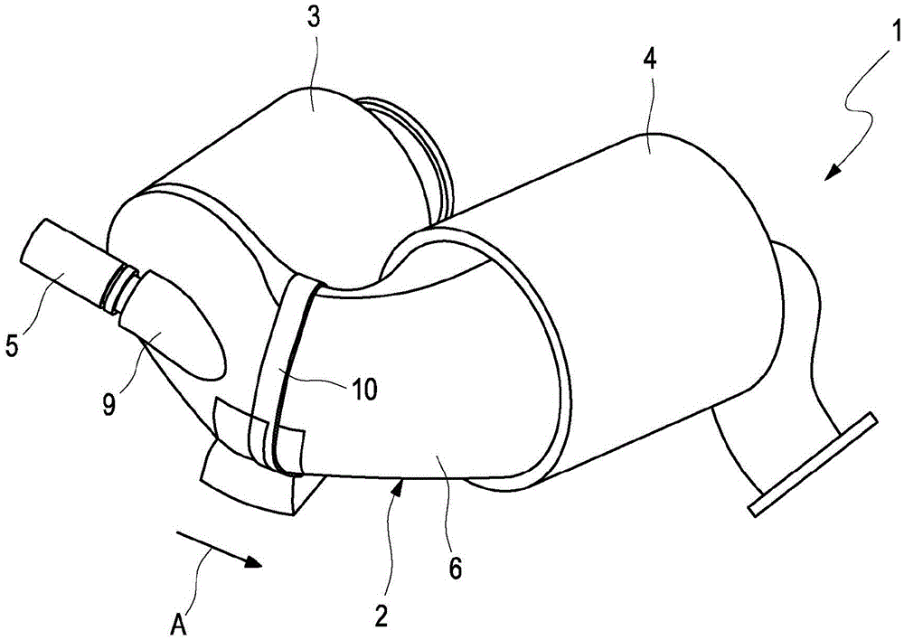
[0024] Motor vehicles with an internal combustion engine, preferably a diesel internal combustion engine, in the figure 1 The exhaust system 1 , which is only partially shown in FIG. 2 , comprises an exhaust pipe 2 extending from the internal combustion engine to the exhaust system. The exhaust gas passing through the exhaust pipe 2 flows through the front catalytic converter 3 and in the exhaust gas flow direction ( figure 1 The SCR catalytic converter 4 arranged downstream of the front catalytic converter on the arrow A) in the figure, in which the nitrogen oxides are selectively catalytically reduced by means of the liquid reducing agent previously fed into the exhaust pipe 2 .

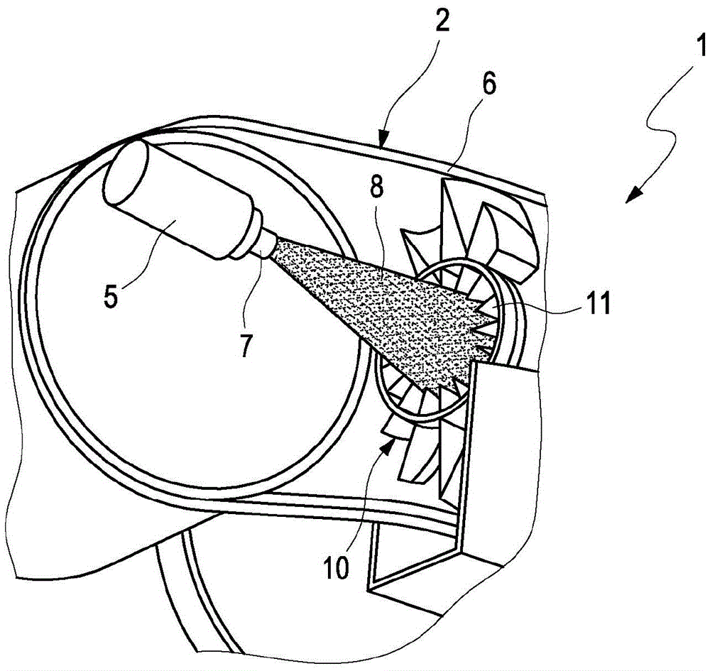
[0025] The liquid reducing agent is, for example, an aqueous urea solution known as AdBlue, which is carried in a reducing agent tank (not shown) in the motor vehicle and is dosed into the exhaust pipe 2 by means of a dosing unit 5 is arranged in the for example U-shaped curved pipe section 6 betw...


PUM

PropertyMeasurementUnit
thicknessaaaaaaaaaa

Abstract

An exhaust device (1) for an internal combustion engine includes an injection nozzle (7) for injecting a liquid reductant into exhaust gas streaming through the exhaust device (1). A mixer (10) is arranged in the exhaust-gas stream for swirling and dispersing the liquid reductant in the exhaust-gas stream. The mixer (10) is provided with a heat-resistant, wear-resistant and corrosion-resistant non-stick coating (18) which is made of a glass or ceramic material (19) to promote rolling off of the reductant. A SCR catalyst (4) is arranged downstream of the mixer (10) for selective catalytic reduction of nitrogen oxides with the aid of the reductant or decomposition products of the reductant.

Description

technical field [0001] The invention relates to an exhaust device for an internal combustion engine having: nozzles for injecting a liquid reducing agent into the exhaust gas flowing through the exhaust device; a mixer in which the liquid reductant is swirled and distributed in the exhaust flow; and an SCR catalyst arranged in the exhaust flow after the mixer for selectively utilizing the reductant or the decomposition products of the reductant Catalytic reduction of nitrogen oxides. Background technique [0002] In the exhaust system of modern motor vehicles, the exhaust gas of internal combustion engines, for example designed as diesel internal combustion engines, is often subjected to selective catalytic reduction (SCR) in order to reduce the nitrogen oxide content. For this purpose, a liquid reducing agent, for example in the form of an aqueous urea solution, also known as AdBlue (diesel exhaust fluid; automotive urea), is carried in the motor vehicle and sprayed into t...

Claims


Application Information

Patent Timeline
Patent Type & Authority Applications(China)
IPC IPC(8): F01N3/28F01N3/10
CPCF01N3/10F01N3/28F01N2510/08F01N2510/10F01N2610/1453F01N3/2066F01N13/16F01N3/2892F01N2610/02Y02T10/12B01F23/2132B01F25/3141B01F25/4316B01F25/431974
Inventor D·沃尔法特
Owner AUDI AG
Why Eureka
Try Eureka