Portable ultrasonic calendering tool

A calendering knife, portable technology, applied in metal processing machinery parts, maintenance and safety accessories, metal processing equipment and other directions, can solve the problems of large damage to the guide rail of the machine tool transmission mechanism, damage to the accuracy and life of the machine tool, and difficulty in mastering the rolling process. , to achieve the effect of easy replacement of the calendering head, saving coolant, and small loss

Inactive Publication Date: 2016-07-06
郭明利 +1
View PDF7 Cites 8 Cited by
  • Summary
  • Abstract
  • Description
  • Claims
  • Application Information

AI Technical Summary

Problems solved by technology

However, since the hardness of the rolling body of the calendering knife is greater than the metal hardness of the processed surface, the metal on the processed metal surface can be plastically deformed to achieve the calendering effect, and the rolling body itself is severely worn, so the rolling body is generally made of alloy steel, tungsten Hard and brittle materials such as steel, diamond, ceramics, etc., the tool life is short, easily damaged, and the overall cost of use is high
At the same time, because calendering will produce a hardened layer on the surface of the workpiece, this layer and the internal material will have obvious delamination, which will easily cause the surface layer to fall off; the rolling process is difficult to master, and improper handling will easily lead to waste products; Large, generally 1000N-3000N, so it will cause great damage to the guide rail of the transmission mechanism of the machine tool, and seriously damage the accuracy and life of the machine tool

Method used


Image

  • Portable ultrasonic calendering tool
  • Portable ultrasonic calendering tool
  • Portable ultrasonic calendering tool

Examples


Embodiment Construction

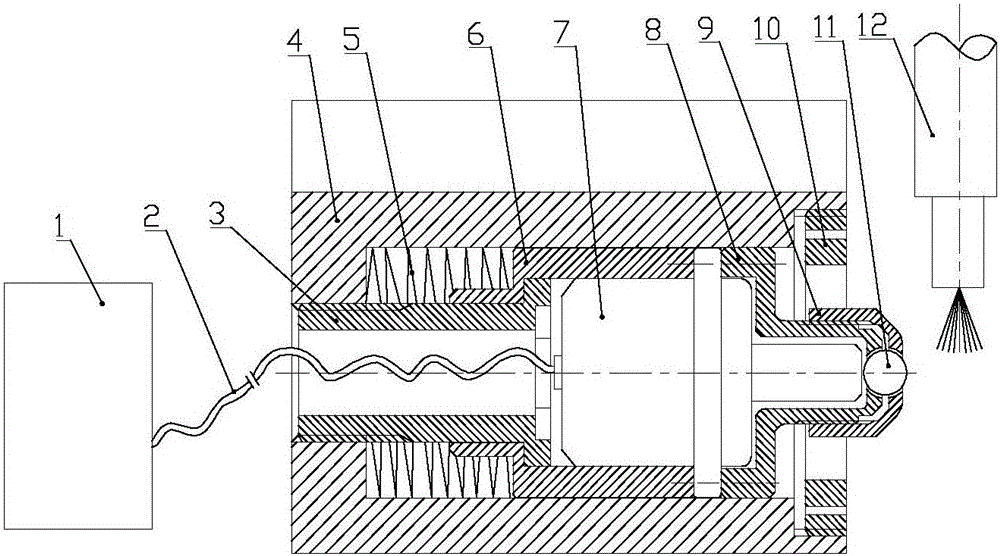
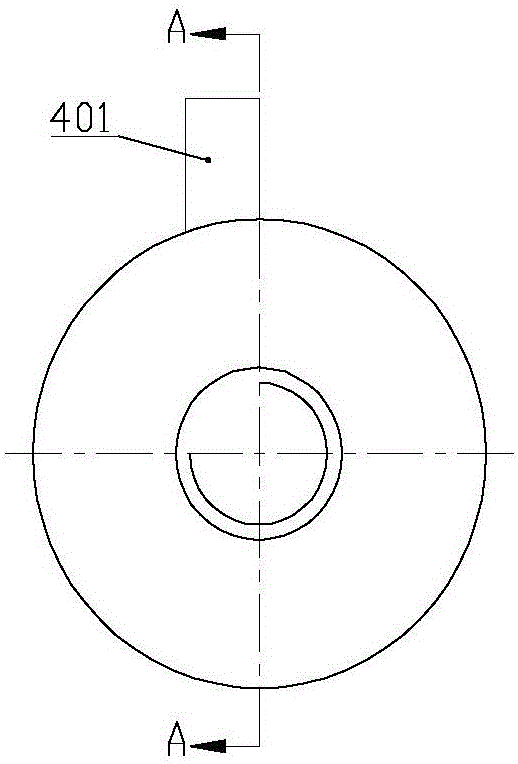
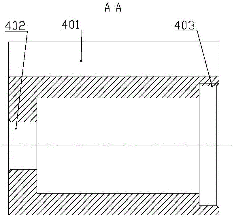
[0026] Such as Figure 1 to Figure 3 , Image 6 , Figure 7 As shown, the portable ultrasonic calender includes an outer sleeve 4, an inner sleeve 6, an ultrasonic transducer 7, a rolling element 11, and an oil mist lubrication device 12. The outer sleeve 4 and the inner sleeve 6 are cylindrical cylinders with one end open, and the outer wall of the outer sleeve 4 A clamping block 401 is provided on the upper part of the outer sleeve 4, a threaded hole 402 is provided at the center of the bottom of the cylinder body; the inner sleeve 6 is provided with a central hole at the center of the cylinder bottom, and the inner sleeve 6 is placed in the outer sleeve 4 with the open end facing outwards. There is a gap between the outer circumference and the inner wall of the cylindrical cavity of the outer sleeve 4. A spring 5 is arranged between the bottom of the outer sleeve 4 and the bottom of the inner sleeve 6; the inner sleeve 6 is placed in the outer sleeve 4 to form an elastic expan...


PUM

PropertyMeasurementUnit
particle sizeaaaaaaaaaa

Abstract

The invention discloses a portable ultrasonic calendering tool. An inner sleeve (6) is disposed in an outer sleeve (4) to form an elastic telescopic mechanism through a spring (5); an ultrasonic transducer (701) is disposed in the inner sleeve (6) and electrically connected with an ultrasonic generator (1) through a cable (2); a luffing bar (703) is inside a roller supporting sleeve (8) after extending out of the inner sleeve (6), a roller adjusting nut (9) is in threaded connection to the front end of the roller supporting sleeve (8), a roller receiving cavity is formed between the roller supporting sleeve (8) and the roller adjusting nut (9), the front end of the a roller (11) contacts the surface of a workpiece, and the rear end of the roller (11) contacts the front end of the luffing bar (703); the invention has the advantages that finishing after composite ultrasonic treatment with the calendering tool is effective, pressure stress is generated on the surface of a part that is calendered, cutting resistance is greatly reduced and vibrational impact on a machine tool is reduced.

Description

Technical field [0001] The patent of the invention relates to a machine tool tool, especially a portable ultrasonic calendering tool. Background technique [0002] No matter what kind of metal processing tool is used for processing, there will always be fine uneven knife marks on the surface of the part, and the phenomenon of interlaced peaks and valleys; the calender knife uses the principle of mechanical extrusion to obtain a mirror-like metal surface A mechanical non-cutting plastic processing method; as a part surface finishing tool, the calender uses the plastic deformation of the metal at room temperature to flatten the microscopic unevenness of the surface of the workpiece to change the surface structure, mechanical characteristics, shape and size the goal of. The calendering tool exerts a certain pressure on the surface of the workpiece to cause the surface metal of the workpiece to produce plastic flow, and fill it into the original residual low concave trough, so as to...

Claims


Application Information

Patent Timeline
Patent Type & Authority Applications(China)
IPC IPC(8): B23P9/04B23Q11/10
CPCB23P9/02B23Q11/10
Inventor 白永红
Owner 郭明利
Why Eureka
Try Eureka