Variable cross-section channel structure of low-power cusped magnetic field plasma thruster

A tangential magnetic field and plasma technology, applied in the field of variable cross-section channel structure, can solve the problems of intensified interaction between plasma and wall surface, performance degradation, insufficient ionization of flux density, etc., to reduce plume divergence angle and reduce ignition voltage , the effect of increasing the ionization rate

Inactive Publication Date: 2016-07-06
HARBIN INST OF TECH
View PDF4 Cites 19 Cited by
  • Summary
  • Abstract
  • Description
  • Claims
  • Application Information

AI Technical Summary

Problems solved by technology

[0004] The present invention aims to solve the problem that under the low power working condition of the existing tangential magnetic field plasma thruster, the insufficient ionization leads to performanc...

Method used


Image

  • Variable cross-section channel structure of low-power cusped magnetic field plasma thruster
  • Variable cross-section channel structure of low-power cusped magnetic field plasma thruster
  • Variable cross-section channel structure of low-power cusped magnetic field plasma thruster

Examples


specific Embodiment approach 1

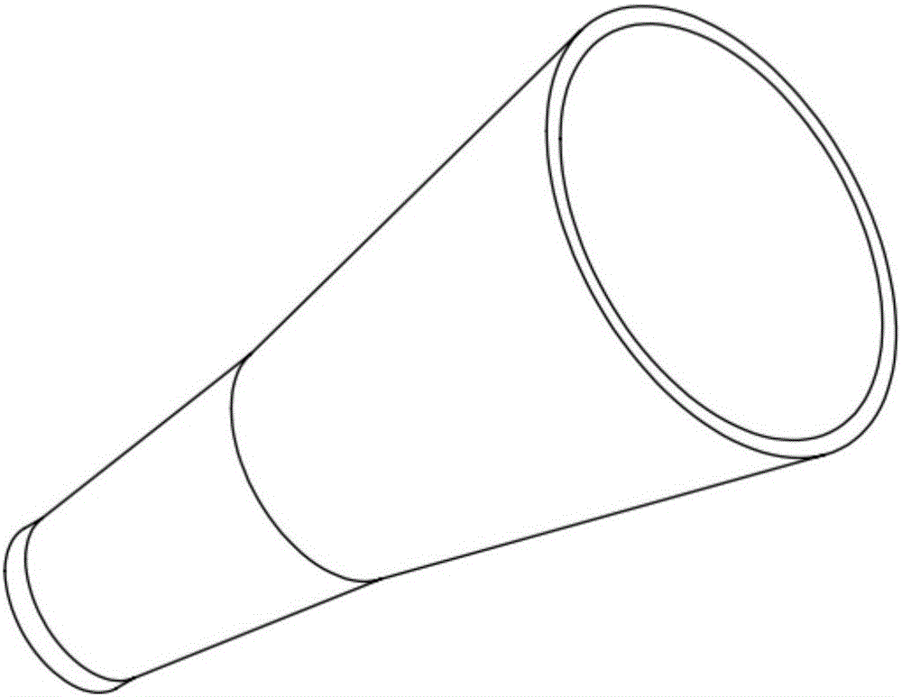
[0016] Specific implementation mode one: refer to Figure 1 to Figure 3 Specifically explain this embodiment, a variable cross-section channel structure of a low-power tangent magnetic field plasma thruster described in this embodiment, the channel is constructed by a ceramic channel and a permanent magnet,

[0017] The ceramic channel is a one-piece structure, which is divided into two sections: the upstream part of the channel and the downstream part of the channel.

[0018] The one-piece structure is a channel structure gradually expanding from the upstream part of the channel to the downstream part of the channel. The outer wall of the ceramic channel is used to achieve clearance fit with the inner wall of the permanent magnet.

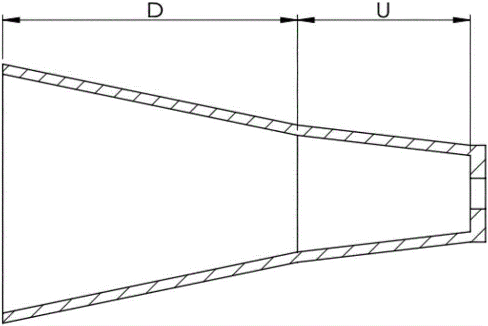
[0019] The expansion angle range of the upstream part of the channel is 0° to 20°, and the expansion angle range of the downstream part of the channel is 10° to 30°.

[0020] In this embodiment, if figure 1 and figure 2 As shown, both the cera...

specific Embodiment approach 2

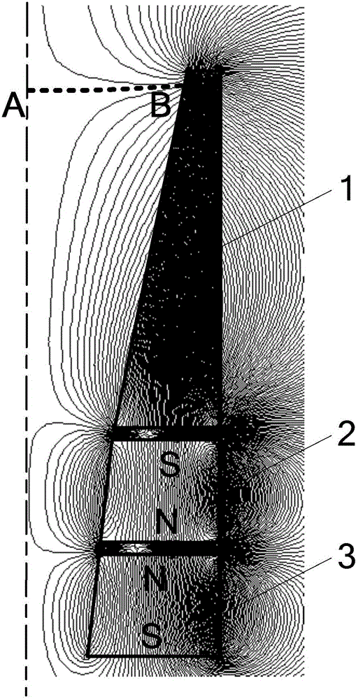
[0021] Specific implementation mode two: refer to Figure 4 Describe this embodiment in detail. This embodiment is a further description of the variable cross-section channel structure of a low-power tangent magnetic field plasma thruster described in Embodiment 1. In this embodiment, the permanent magnet includes a first-stage permanent magnet. 1. The second-level permanent magnet 2 and the third-level permanent magnet 3, the first-level permanent magnet 1, the second-level permanent magnet 2 and the third-level permanent magnet 3 are arranged sequentially from the downstream to the upstream of the channel; the three permanent magnets are magnetized along the axial direction, And the magnetization directions of two adjacent permanent magnets are opposite;

[0022] The inner wall surface of the first-stage permanent magnet 1 and the outer wall surface of the downstream part of the channel realize clearance fit, and the length of the first-stage permanent magnet 1 is the same a...

specific Embodiment approach 3

[0026] Embodiment 3: This embodiment is a further description of the variable cross-section channel structure of a low-power tangent magnetic field plasma thruster described in Embodiment 1. In this embodiment, the material of the ceramic channel is boron nitride Ceramic, the wall thickness is 2mm, the minimum inner diameter of the upstream part of the channel is 15mm, the inner diameter of the outlet is 47mm, the expansion angle of the upstream part of the channel is 13°, and the expansion angle of the downstream part of the channel is 22°.

[0027] In this embodiment, the axial length of the upstream part U of the channel is the same as the total length of the second-stage permanent magnet 2 and the third-stage permanent magnet 3, and the axial length of the downstream part D of the channel is the same as the length of the first-stage permanent magnet 1, that is, the two expansion angles of the channel The interface corresponds to the second magnetic tip of the magnetic field...


PUM

PropertyMeasurementUnit
Wall thicknessaaaaaaaaaa
The inside diameter ofaaaaaaaaaa
Minimum inner diameteraaaaaaaaaa

Abstract

The invention relates to a variable cross-section channel structure of a low-power cusp magnetic field plasma thruster, which relates to the field of cusp magnetic field plasma thrusters. The present invention aims to solve the problem that under the low power working condition of the existing tangential magnetic field plasma thruster, the insufficient ionization leads to performance degradation when the current density is low, and the performance degradation is also caused by the intensified interaction between the plasma and the wall surface when the current density is high. The problem. The channel is constructed by a ceramic channel and a permanent magnet. The ceramic channel is a one-piece structure, which is divided into two sections: the upstream part of the channel and the downstream part of the channel. The channel structure gradually expands from the upstream part of the channel to the downstream part of the channel. The outer wall of the ceramic channel is used for To achieve clearance fit with the inner wall of the permanent magnet. This structure increases the atomic density and ionization rate in the upstream ionization area, and at the same time reduces the interaction with the channel wall during the accelerated ejection of ions generated by ionization, prolonging the life of the thruster. It is used in the low power working condition of the tangent magnetic field plasma thruster.

Description

technical field [0001] The invention relates to a variable-section channel structure of a low-power cusp magnetic field plasma thruster. It belongs to the field of tangential magnetic field plasma thrusters. Background technique [0002] Electric propulsion is gradually favored by the aerospace industry due to its advantages such as high specific impulse, long life, compact structure, small size and light pollution. have an important role. The cusped magnetic field plasma thruster is a new type of electric propulsion concept emerging internationally. Different from the traditional Hall thruster, the cusped magnetic field plasma thruster relies on multi-stage permanent magnets to form a cusped magnetic field. Among them, the adjacent The polarities of the two permanent magnets are opposite. The anode is placed upstream of the ceramic discharge channel, and the hollow cathode is placed at the outlet. After the working fluid enters the channel through the upstream gas distrib...

Claims


Application Information

Patent Timeline
IPC IPC(8): F03H1/00
CPCF03H1/0081
Inventor 刘辉陈蓬勃胡鹏孙强强于达仁
Owner HARBIN INST OF TECH
Why Eureka
Try Eureka