Magnetic suspension-type centrifugal electrostatic spinning device

A technology of electrospinning and centrifugal spinning, applied in textile and papermaking, filament/thread forming, fiber processing, etc., can solve the problems of low safety performance, high cost, complicated operation, etc. The effect of less kinetic energy loss and convenient operation

Active Publication Date: 2016-07-13
BEIJING UNIV OF CHEM TECH
View PDF6 Cites 3 Cited by
  • Summary
  • Abstract
  • Description
  • Claims
  • Application Information

AI Technical Summary

Problems solved by technology

The fibers prepared by the melt electrospinning method are relatively thick, and the research progress and industrialization development are slow; the centrifugal spinning method requires a high-speed motor to maintain the high-speed rotation of the disc in order to achieve continuous spinning conditions, and the entire process consumes more electricity. The structure of the device is complicated, the operation is cumbersome, the safety performance is low, and the diameter of the prepared fiber is relatively thick
[0003] Regardless of the electrospinning method or the centrifugal spinning method, researchers have never stopped the research and development and improvement of technology, but most of them simply improve the centrifugal spinning process or the electrospinning nozzle, which has never been able to solve the problem
Chinese patent (patent number: ZL201410108867.9) drives the liquid storage device to rotate through the driving device, and the liquid is centrifugally spun under the centrifugal force. Although the output of the device is high, the structure is complex, the power loss is large, and the cost is relatively high.

Method used


Image

  • Magnetic suspension-type centrifugal electrostatic spinning device
  • Magnetic suspension-type centrifugal electrostatic spinning device

Examples


Embodiment Construction

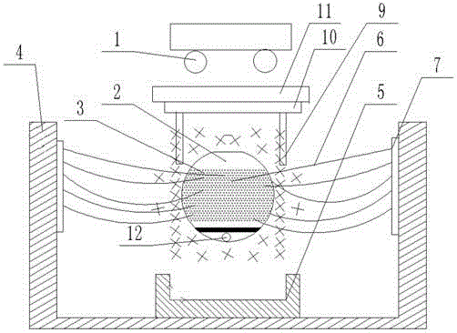
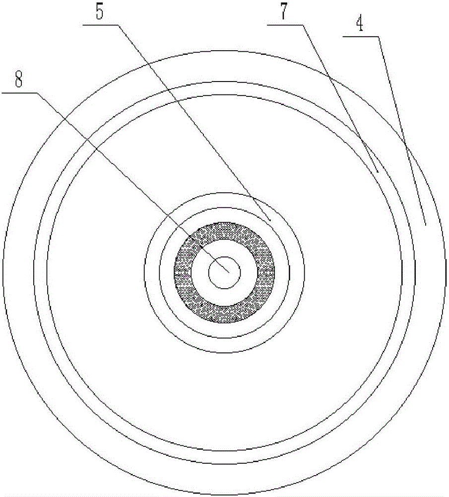
[0020] A kind of magnetic levitation type centrifugal electrospinning device of the present invention, such as figure 1 As shown, it mainly includes an infrared heating tube 1, a magnetic levitation ball 2, a collection cylinder 4, a magnetic levitation base 5, a cylindrical electrode 7, a triangular clamping device 9, a high-speed rotating disc 10, a support frame 11 and a counterweight ball 12. The magnetic levitation ball 2 is a hollow sphere. There is a feeding hole 8 on the top of the magnetic levitation ball 2. There are multiple circles of centrifugal spinning holes 3 near the waist of the magnetic levitation ball 2. The lower part of the magnetic levitation ball 2 has a counterweight. The small ball 12 is placed on the bottom surface of the collection cylinder 4 with a magnetic levitation base 5, the magnetic levitation ball 2 is located directly above the magnetic levitation base 5, and the support frame 11 above the magnetic levitation ball 2 is sequentially installed...


PUM


Abstract

The invention relates to a magnetic suspension-type centrifugal electrostatic spinning device, and belongs to the field of spinning.The magnetic suspension-type centrifugal electrostatic spinning device comprises infrared heating tubes, a small magnetic suspension ball, a collection cylinder, a magnetic suspension base, a cylindrical electrode, triangular clamping devices, a high-speed rotating disc, a support frame and a small counterweight ball; the small magnetic suspension ball is a hollow sphere and provided with a feeding hole, multiple circles of centrifugal spinning holes are formed in the portion near the waist of the small magnetic suspension ball, the counterweight ball is arranged on the lower portion of the small magnetic suspension ball, the magnetic suspension base is arranged on the bottom face of the collection cylinder, the small magnetic suspension ball is located over the magnetic suspension base, the triangular clamping devices, the high-speed rotating disc and the infrared heating tubes are sequentially installed on the support frame above the small magnetic suspension ball, and the cylindrical electrode is located in the middle of the inner wall of the collection cylinder.The holes are distributed on the whole small hollow metal ball, when a higher speed V is given to the small magnetic suspension ball, a melt in the small magnetic suspension ball is tossed out, centrifugal spinning is conducted, and the kinetic energy loss in the rotating process of the small metal magnetic suspension ball is less.

Description

technical field [0001] The invention relates to a magnetic levitation centrifugal electrostatic spinning device, which belongs to the field of centrifugal electrostatic spinning. Background technique [0002] With the rapid development of nanotechnology, the research field of nanomaterials has been widely concerned, and the demand for nanofibers is also increasing. At present, there are many methods for preparing nanofibers, mainly including electrospinning, centrifugal spinning, stretching and two-component composite spinning. Electrospinning is a process in which a charged polymer solution or polarized melt forms a Taylor cone in an electrostatic field, forms a jet flow on the Taylor cone, and then refines it by solvent evaporation or melt cooling and solidification to obtain a fibrous substance. Process; Centrifugal spinning method is a method in which polymer melt is thrown out from pores to form fibers by means of centrifugal force and shear force generated by a high-s...

Claims


Application Information

Patent Timeline
Patent Type & Authority Applications(China)
IPC IPC(8): D01D5/00
CPCD01D5/0023D01D5/0061D01D5/0069D01D5/0092
Inventor 杨卫民马小路李好义张莉彦阎华谭晶焦志伟谢鹏程丁玉梅
Owner BEIJING UNIV OF CHEM TECH
Why Eureka
Try Eureka