Detachable pedicle screw

A pedicle screw and detachable technology, applied in the field of pedicle screws, can solve the problems of increasing the economic burden of patients, increasing the pain of patients, hindering the reconstruction of trabecular bone, etc., to restore the structure and mechanical conduction characteristics, and avoid pain. and economic burden, and the effect of reducing the incidence of complications

Inactive Publication Date: 2016-07-20
陈卫 +1
View PDF9 Cites 3 Cited by
  • Summary
  • Abstract
  • Description
  • Claims
  • Application Information

AI Technical Summary

Problems solved by technology

However, the implantation of internal fixation after fracture will further damage the trabecular bone structure. The existence of internal fixation will hinder the reconstruction of trabecular bone during the fracture healing process, and cannot effectively restore the local normal structure and mechanical conductivity of the bone, which may lead to local stress conce

Method used


Image

  • Detachable pedicle screw
  • Detachable pedicle screw
  • Detachable pedicle screw

Examples


Embodiment 1

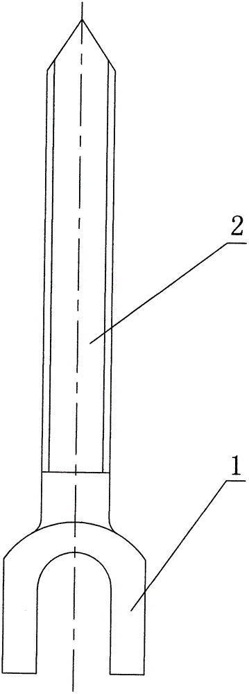
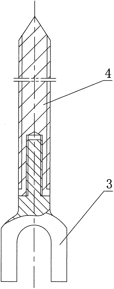
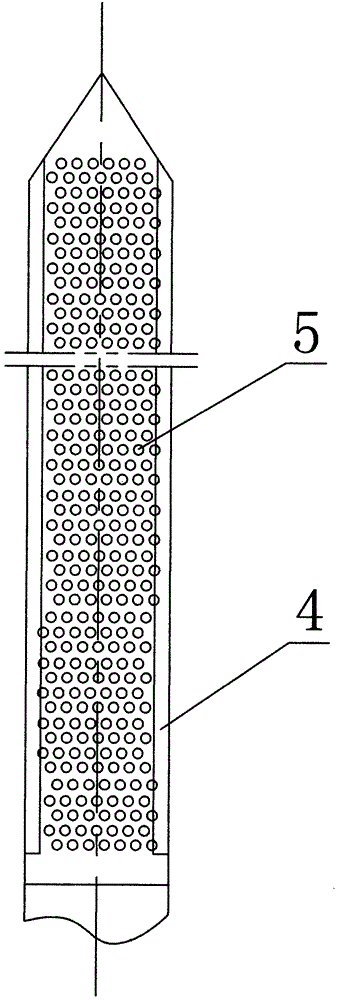
[0023] Embodiment 1: The present invention is an improvement to the existing one-piece pedicle screw, and the structure of the existing pedicle screw is as follows figure 1 As shown, its structure is an integrated structure of the screw body 2 and the nail tail 1 at the end of the screw body 2. The improved detachable screw body and the nail tail are split structures, such as figure 2 , image 3 As shown, a screw hole is provided at the axis of the end of the screw body 4, the screw rod protruding from the front end of the screw tail 3 is screwed with the screw body 4, and micro holes are evenly opened on the screw body 4 and the front end of the nail tail 5. The diameter of the microhole 5 is 1-50um, and the axis of the microhole 5 is perpendicular to the axis of the screw body 4 . After the pedicle screw with the structure of this embodiment is screwed into the pedicle, the axis of the microhole 5 on the screw body 4 is the same as the direction of the trabecular bone in t...

Embodiment 2

[0024] Embodiment 2: as Figure 4 As shown, the difference between this embodiment and Embodiment 1 is that the screw body 4 and the front end of the nail tail are uniformly provided with strip-shaped holes 6, and the axis of the strip-shaped holes 6 is perpendicular to the axis of the screw body. After screwing the pedicle screw of the structure of this embodiment into the pedicle, the axis of the strip-shaped hole 6 on the screw body 4 is the same as the direction of the bone trabecula in the vertebral body, and the strip-shaped opening at the front end of the nail tail 3 is The axis of the hole 6 is the same as the direction of the trabecular bone in the vertebral body, so that the trabecular bone can be distributed along the strip-shaped hole 6 .

Embodiment 3

[0025] Embodiment 3: as Figure 5 , Figure 6 As shown, the difference between this embodiment and Embodiment 1 is that a regular hexagonal groove 7 is provided at the end axis of the screw body 4, a screw hole is provided at the end axis of the screw body 4, and the nail tail 3 and The 4 screw nail bodies are screwed together. Screw the screw body 4 of the structure of the present embodiment into the pedicle with an external hexagonal wrench and adjust the axis of the microhole 5 (or strip hole 6) on the surface to be the same as the direction of the trabecular bone in the vertebral body, and then screw it into the pedicle. Screw tail 3, and make the axis of the microhole 5 (or strip hole 6) provided at the front end of the nail tail 3 be the same as the direction of the trabecular bone in the vertebral body, then the insertion of the pedicle screw with the structure of this embodiment is completed .


PUM

PropertyMeasurementUnit
Pore diameteraaaaaaaaaa

Abstract

The invention discloses a detachable pedicle screw. A screw body and a screw tail adopt a split type structure, micro holes are evenly formed in the screw body and the front end of the screw tail, and the axes of the micro holes are perpendicular to that of the screw body. The pedicle screw adopts the split type structure, namely, a spinning structure, a clamping structure, an insertion structure and the like, the screw body and the screw tail are made of magnesium alloys having advantages of degradability, biocompatibility and the like, meanwhile, the micro holes perpendicular to the axis of the screw body are formed in the screw body and the front end of the screw tail, so that bone trabeculae can be distributed along the micro holes, synchronous reconstruction of the bone trabeculae is allowed during fracture healing, the continuity of the bone trabeculae in vertebrae is recovered, dual healing of fracture cortex and spongiosa is realized, the structure and mechanical conduction features are effectively recovered, the internal fixation complication incidence can be significantly reduced, the fracture treatment effect can be improved, peripheral soft tissue and blood circulation can be effectively protected, the internal fixator related complication occurrence risk is reduced, and pain and economic burden caused by secondary major surgery on patients are avoided.

Description

technical field [0001] The present invention relates to pedicle screws. Background technique [0002] The pedicle is the strongest part of the spine and is the effective point of action for manipulating and immobilizing the spine during vertebral fracture surgery. Pedicle instruments can maintain the normal anatomy of the spine while obtaining effective fixation, and preserve the motion segments of the spine to the greatest extent. At different levels of the same instrument, retraction, compression, rotation, restoration of lordosis, and anterior and posterior translation of the vertebral body can be performed, respectively. It is effective in controlling abnormal activities in all directions, including rotational activities, and because the pedicle instrument has a good stabilizing effect on the three columns and its own versatility, it is also very reliable in maintaining and rebuilding the physiological lordosis of the lumbar spine . There are important bone trabecular...

Claims


Application Information

Patent Timeline
IPC IPC(8): A61B17/68A61B17/70A61B17/86
CPCA61B17/683A61B17/685A61B17/7064A61B17/7074A61B17/8625A61B17/8635A61B2017/564
Inventor 魏宁马雷常文利杜晨光张柳吴新宝董天华陈伟张英泽
Owner 陈卫
Why Eureka
Try Eureka