A magnetic separation method and device based on a microfluidic channel

A microfluidic channel and magnetic separation device technology, applied in fluid controllers, chemical instruments and methods, laboratory containers, etc. Separation, non-target biological inclusions, etc., to achieve the effect of reducing agglomeration, simple structure, and enhancing gradient magnetic field

Active Publication Date: 2017-09-29
HUAZHONG UNIV OF SCI & TECH
View PDF6 Cites 0 Cited by
  • Summary
  • Abstract
  • Description
  • Claims
  • Application Information

AI Technical Summary

Problems solved by technology

[0005] (1) The agglomeration behavior between magnetic particles can cause non-target organisms to be mechanically included in the aggregate and affect the separation accuracy;
[0006] (2) In the microfluidic chip separation system, the magnetic particle aggregates are easily trapped and easily cause microchannel blockage;
[0007] (3) The agglomeration behavior between different magnetic particles makes the system unable to achieve effective separation of multiple targets according to the differences in the physical properties of the particles themselves (such as particle size, magnetic susceptibility, etc.)
[0008] The above problems cause the system to only separate particles with a concentration lower than 0.1%, which affects the separation efficiency and restricts the application and development of high-precision magnetophoretic separation technology

Method used


Image

  • A magnetic separation method and device based on a microfluidic channel
  • A magnetic separation method and device based on a microfluidic channel
  • A magnetic separation method and device based on a microfluidic channel

Examples


Embodiment 1

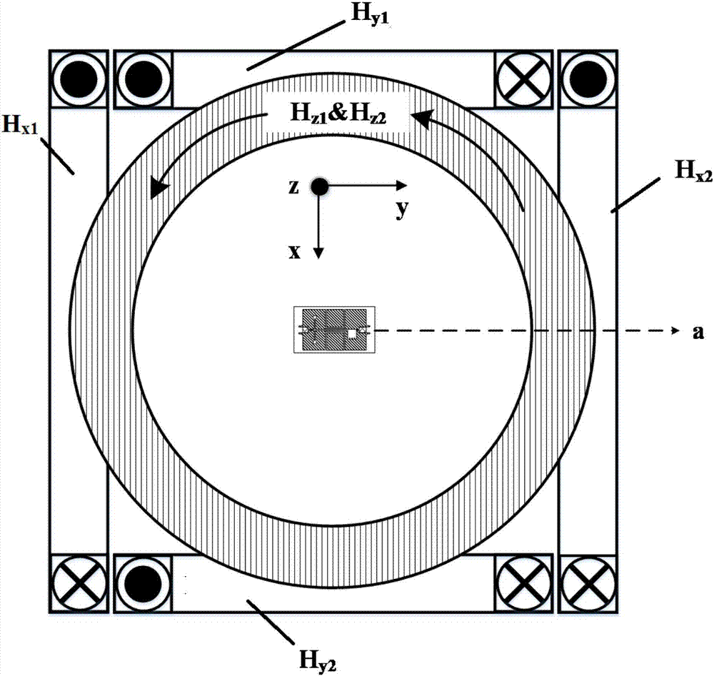
[0066] The magnetic separation device of this embodiment includes a three-axis Helmholtz coil and a microfluidic chip a, the main body of the three-axis Helmholtz coil is supported by a screw, and the microfluidic chip is placed on a micro-elevator, so that the microfluidic The chip is located in the central area of ​​the three-axis Helmholtz coil and parallel to the z-axis coil. The cross-sectional schematic diagram of the device at the microfluidic chip is shown in figure 1 As shown, you can see the y-axis coil H y1 and H y2 Set at the rear and front, the x-axis coil H x1 and H x2 It is arranged on the left and right sides, and the z-axis coil is arranged on the upper and lower sides of the microfluidic chip in parallel.

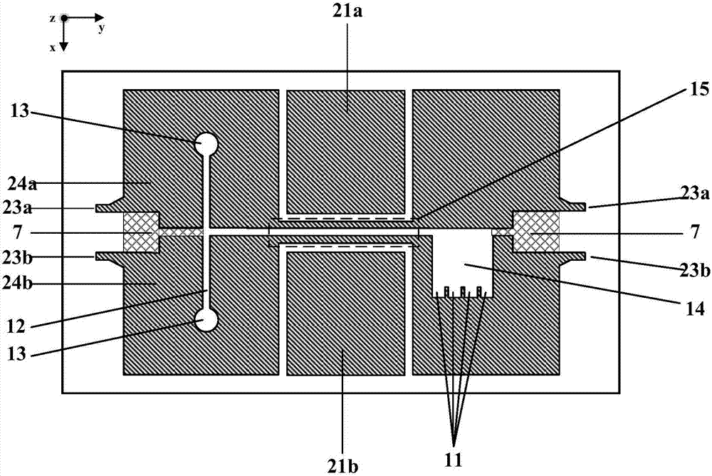
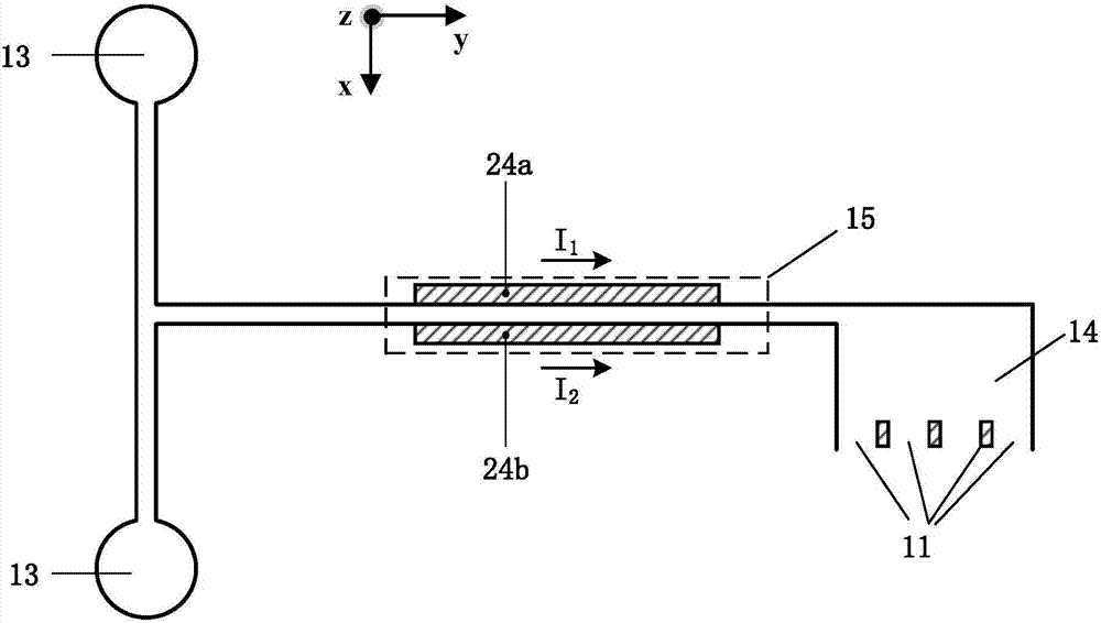
[0067] Among them, the structure of the microfluidic chip a is as follows figure 2 shown, including solid copper areas. The copper-clad area 24a can be externally connected to an electrical signal through the electrode 23a, and the copper-clad area ...


PUM


Abstract

The invention discloses a magnetic separation method and device based on a microfluidic channel. The method comprises the steps of controlling sample liquid to flow into the microfluidic channel; applying a gradient magnetic field perpendicular to the microfluidic channel to the sample liquid in the microfluidic channel, so that different particles in the sample liquid are separated; applying a static uniform magnetic field to the sample liquid in the microfluidic channel; applying a periodical uniform magnetic field to the sample liquid in the microfluidic channel, wherein the gradient magnetic field, the periodical uniform magnetic field and the static uniform magnetic field act together to generate a vibration composite gradient magnetic field to avoid aggregation of different particles in the sample liquid, the microfluidic channel, the gradient magnetic field and the static uniform magnetic field are located in the xy plane, and the periodical uniform magnetic field is perpendicular to the xy plane. The magnetic separation method is easy to control, good in depolymerization effect, high in economical efficiency and capable of greatly pushing the research of methods for high-precision separation of magnetic particles in a microchip magnetophoresis separation system.

Description

technical field [0001] The invention belongs to the field of microfluidic chips, and more specifically relates to a magnetic separation method and device based on a microfluidic channel. Background technique [0002] With the advancement of micro-electromechanical systems and micro-nano technology, bio-separation technology based on microfluidic chip systems has developed rapidly. Compared with traditional technology, it has the advantages of low sample volume, high detection speed, high precision and controllability, and has become an important means of bioseparation technology research at present. It is used in cell separation, protein and nucleic acid separation and purification, etc. The field shows broad application prospects. [0003] At the micro scale, magnetophoretic separation technology, which uses magnetic field force to induce directional movement of magnetic micro / nanoparticles to achieve fine separation, is an important biological separation method developed ...

Claims


Application Information

Patent Timeline
Patent Type & Authority Patents(China)
IPC IPC(8): B01L3/00
CPCB01L3/5027B01L3/502761B01L2400/043
Inventor 韩小涛曹全梁冯洋王桢张绍哲李亮
Owner HUAZHONG UNIV OF SCI & TECH
Why Eureka
Try Eureka