Method for improving quality of laser metal 3D formed part

A technology of formed parts and laser, which is applied in the direction of improving energy efficiency, process efficiency, additive manufacturing, etc., can solve problems such as unavoidable powder sticking, inability to accumulate thin-walled parts, low energy density, etc., to reduce surface roughness, The effect of reducing surface roughness and improving quality

Active Publication Date: 2016-07-20
苏州柯莱得激光科技有限公司
View PDF8 Cites 5 Cited by
  • Summary
  • Abstract
  • Description
  • Claims
  • Application Information

AI Technical Summary

Problems solved by technology

However, there are still problems with this method: it is still difficult to avoid powder sticking on the outer surface of the formed part; it is not possible to stack narrow thin-walled parts; stacking efficiency etc.
[0005] In the traditional optical external coaxial powder feeding structure, the laser scanning energy has a Gaussian distribution, and the energy density on both sides of the melting channel is low, resulting in uneven cladding layers on both sides, easy to shrink and crack, and powder adhering to the surface is not easy melt

Method used


Image

  • Method for improving quality of laser metal 3D formed part
  • Method for improving quality of laser metal 3D formed part
  • Method for improving quality of laser metal 3D formed part

Examples


Embodiment

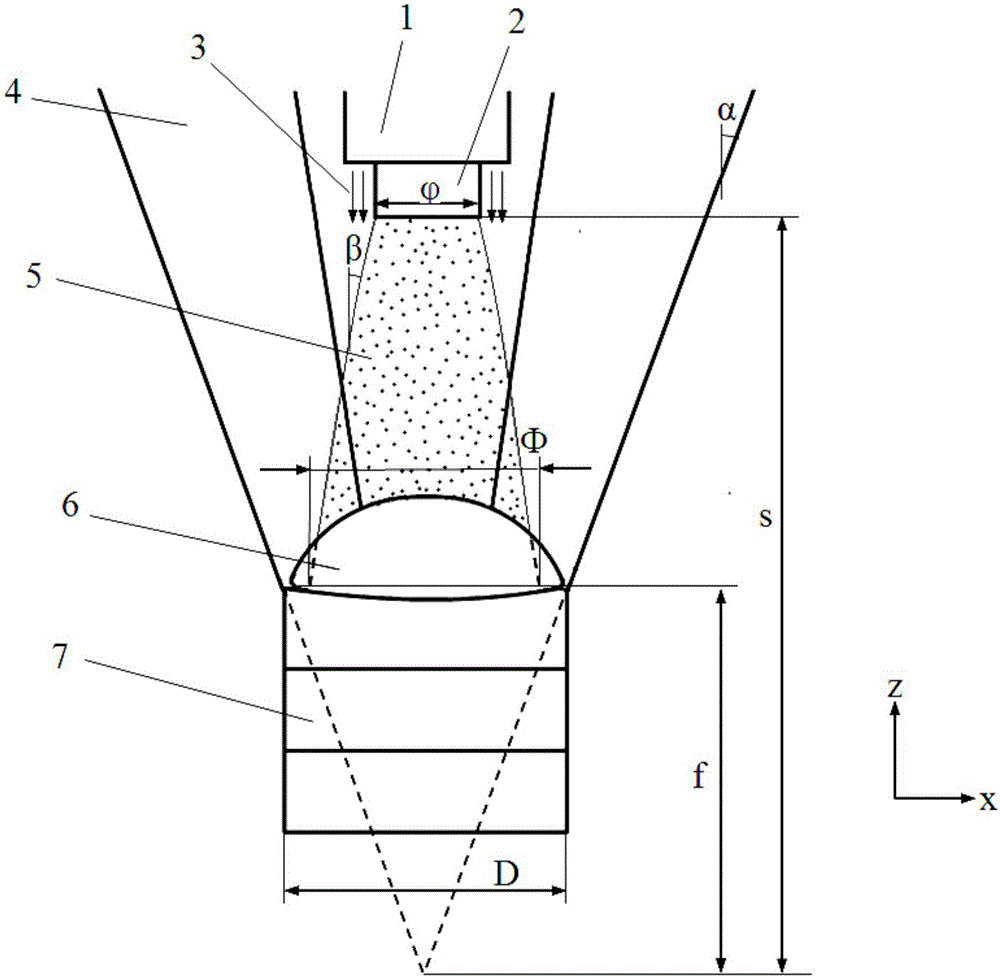
[0024] The powder material is selected as Fe313, the particle size is 75μm-106μm, the laser power is 600W, the powder feeding volume is 8g / min, the scanning speed is 7mm / s, and the protective air pressure is 1.5bar. The parameters of the selected hollow laser cladding nozzle are: s=18mm, α=20°, . The negative defocus amount f is adjusted to 3.5mm, and the measured β value is about 5°. According to the expression D=f×2tan(α) of the outer diameter of the spot, the expression of the powder spot diameter Φ Thus, D:Φ=0.7635>0.7 can be obtained. The average surface roughness of the molded part was measured to be Ra=1.195 μm.

[0025] The present invention adopts the hollow laser internal powder feeding cladding nozzle, the laser beam is distributed in a circular focus, and its scanning energy distribution is saddle-shaped, which is more uniform than the Gaussian distribution, the cladding layers on both sides can be fully melted, and the surface roughness is reduced; The powd...


PUM


Abstract

The invention discloses a method for improving the quality of a laser metal 3D formed part. A hollow laser inner powder delivery cladding spray head is selected; according to the cladding spray head, a powder pipe and a collimation protective gas pipe located on the periphery of the powder pipe are arranged in the middle of leaser beams; the leaser beams are annularly distributed in a focused manner, powder beams are located in the middle, a collimation protective gas curtain is formed around the powder beams, and therefore the laser beams annularly distributed in the focused manner, the collimation protective gas curtain and the powder beams are coaxial; and the part is placed on the negative defocusing position, the laser beams act on the surface of the part to form a weld pool, the cladding spray head moves in the Z-axis direction, and the negative defocusing amount of the laser beams is adjusted, and the ratio of the outer diameter D of light spots reaching the weld pool to the diameter phi of powder spots reaching the weld pool is made to be larger than 0.7. By the adoption of the method, laser scanning energy distribution is more uniform, the edge of the cladding layer can be fully molten, the amount of powder adhering to the side of the formed part can be reduced greatly, the roughness of the surface of the metal formed part is lowered, and the quality of the metal formed part is improved.

Description

technical field [0001] The invention relates to the technical field of laser rapid prototyping, in particular to a method for improving the quality of laser metal 3D forming parts. Background technique [0002] Laser metal rapid prototyping technology is based on laser cladding technology and rapid prototyping technology. Generally, the laser cladding nozzle is clamped by a moving mechanism, and the laser is used as a heat source to synchronously transport the metal powder / wire, which is rapidly melted and cooled at the molten pool on the substrate. Slice the 3D CAD model layer by layer, plan the motion path, and then use the above laser cladding method to stack layers into a solid body. It has the advantages of no mold, short forming time, capable of forming complex structures, capable of forming gradient materials, unlimited forming size, metallurgical bonding between layers, and uniform and dense microstructure. It has wide application in aerospace, national defense, med...

Claims


Application Information

Patent Timeline
IPC IPC(8): B22F3/105B33Y10/00B33Y30/00
CPCB22F3/003B33Y10/00B33Y30/00B22F10/00B22F10/36B22F10/32B22F10/25B22F10/38B22F12/53Y02P10/25
Inventor 石拓金朝龙石世宏
Owner 苏州柯莱得激光科技有限公司
Why Eureka
Try Eureka