Welding device and method for avoiding high-nitrogen steel welding air holes and improving connector strength

A joint strength and welding device technology, which is applied in the direction of welding/welding/cutting articles, welding equipment, laser welding equipment, etc., can solve the problems of coarse weld grains and easy precipitation of carbonitrides, etc., to improve mechanical properties and improve The effect of weld structure and grain refinement

Active Publication Date: 2016-07-20
CHANGCHUN UNIV OF SCI & TECH
View PDF9 Cites 47 Cited by
  • Summary
  • Abstract
  • Description
  • Claims
  • Application Information

AI Technical Summary

Problems solved by technology

[0007] In order to achieve the above object, the present invention provides a welding device that solves the welding porosity of high-nitrogen steel and improves the joint strength, and solves the problems of high-nitrogen steel in the prior art that are prone to gas generation, weld

Method used


Image

  • Welding device and method for avoiding high-nitrogen steel welding air holes and improving connector strength
  • Welding device and method for avoiding high-nitrogen steel welding air holes and improving connector strength
  • Welding device and method for avoiding high-nitrogen steel welding air holes and improving connector strength

Examples


Embodiment 1

[0040] The welding method of the above-mentioned device is specifically carried out in accordance with the following steps:

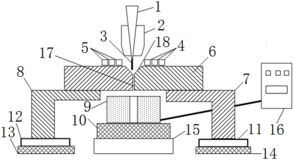
[0041] Step 1: Install and debug the device, clamp two welded workpieces 6 made of high-nitrogen steel with a thickness of 8.0mm and a nitrogen content of 0.5-0.7% on the first workpiece support plate 7 and the second On the workpiece support plate 8;

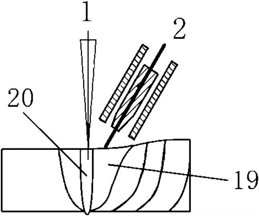
[0042] Step 2: Open the water inlet valves of the first water-passing copper pipe 4 and the second water-passing copper pipe 5, adjust the circulating water temperature in the first water-passing copper pipe 4 and the second water-passing copper pipe 5 to 15°C, and the circulating water flow rate 12L / min; turn on the excitation power supply 16, start the power supply of the CNC workbench, YAG laser and welding torch 2 synchronously, the YAG laser emits a laser beam 1, and the laser beam 1 is irradiated vertically on the front of the welding workpiece 6 to form a laser keyhole 20; welding torch 2 Welding...

Embodiment 2

[0045] The welding method of the above-mentioned device is specifically carried out in accordance with the following steps:

[0046] Step 1: Install and debug the device, clamp two welded workpieces 6 made of high-nitrogen steel with a thickness of 8.0mm and a nitrogen content of 0.5-0.7% on the first workpiece support plate 7 and the second On the workpiece support plate 8;

[0047] Step 2: Open the water inlet valves of the first water-passing copper pipe 4 and the second water-passing copper pipe 5, adjust the circulating water temperature in the first water-passing copper pipe 4 and the second water-passing copper pipe 5 to 10°C, and the circulating water flow rate 15L / min; turn on the excitation power supply 16, start the power supply of the CNC workbench, YAG laser and welding torch 2 synchronously, CO 2 The laser emits a laser beam 1, and the laser beam 1 is vertically irradiated on the front of the welding workpiece 6 to form a laser keyhole 20; the welding torch 2 pe...

Embodiment 3

[0050] The welding method of the above-mentioned device is specifically carried out in accordance with the following steps:

[0051] Step 1: Install and debug the device, clamp two welded workpieces 6 made of high-nitrogen steel with a thickness of 8.0mm and a nitrogen content of 0.5-0.7% on the first workpiece support plate 7 and the second On the workpiece support plate 8;

[0052] Step 2: Open the water inlet valves of the first water-passing copper pipe 4 and the second water-passing copper pipe 5, adjust the circulating water temperature in the first water-passing copper pipe 4 and the second water-passing copper pipe 5 to 20°C, and the circulating water flow rate 10L / min; turn on the excitation power supply 16, start the power supply of the CNC workbench, the YAG laser and the welding torch 2 synchronously, the semiconductor laser emits the laser beam 1, and the laser beam 1 is irradiated vertically on the front of the welding workpiece 6 to form a laser keyhole 20; the ...


PUM

PropertyMeasurementUnit
Diameteraaaaaaaaaa

Abstract

The invention discloses a welding device and method for avoiding high-nitrogen steel welding air holes and improving connector strength, and belongs to the technical field of welding. Two welded workpieces are fixed to a first workpiece supporting plate and a second workpiece supporting plate in a butt joint manner. A welded workpiece connector gap is formed between the two welded workpieces. A groove is formed in the front faces of the welded workpieces and the position of the welded workpiece connector gap. The pipe wall of a first water passing copper pipe and the pipe wall of a second water passing copper pipe are closely attached to the two sides of the groove. Magnet exciting coils are arranged on the back faces of the welded workpieces, a laser beam vertically irradiates the front faces of the welded workpieces, a welding gun is arranged on the front faces of the welded workpieces, and the laser beam, the welded workpiece connector gap and the magnet exciting coils are coaxial. The problems that in the high-nitrogen steel welding process in the prior art, gas is prone to being generated, nitride, carbide and carbonitride are likely to be separated out, and the grain of a weld line is thick are solved, accordingly, the mechanical performance of a high-nitrogen steel welding connector is improved, and the tenacity of a welding heat affected zone is improved.

Description

technical field [0001] The invention belongs to the field of welding technology, and relates to a welding device and a welding method for solving high-nitrogen steel welding porosity and improving joint strength, especially using a magnetic control and temperature control composite method to solve high-nitrogen steel laser-arc composite welding porosity and improving A welding device for joint strength and a welding method thereof. Background technique [0002] High-nitrogen austenitic stainless steel (high-nitrogen steel) is an engineering material that has received widespread attention in recent years. Its N content generally exceeds 0.4%, and the N element is mainly used to partially or completely replace the alloying element Ni to obtain an austenite structure. High nitrogen steel has high strength and toughness, and also has good corrosion resistance. Due to its excellent performance, high nitrogen steel has become an important material in the field of industry and eng...

Claims


Application Information

Patent Timeline
IPC IPC(8): B23K26/348B23K26/60
CPCB23K26/348B23K26/60B23K2103/04
Inventor 刘双宇刘凤德李彦清刘佳张宏石岩陈实现黄根哲徐春鹰
Owner CHANGCHUN UNIV OF SCI & TECH
Why Eureka
Try Eureka