Device for coal pyrolysis gas cooling and waste heat recovery

A technology of waste heat recovery and gas cooling, which is applied in the field of coal chemical industry, can solve the problems of decreased heat transfer efficiency and increased heat transfer surface thermal resistance, and achieves the effects of reducing consumption, reducing heat loss, and easy operation

Inactive Publication Date: 2016-07-20
CHINA NAT HEAVY MACHINERY RES INSTCO
View PDF4 Cites 0 Cited by
  • Summary
  • Abstract
  • Description
  • Claims
  • Application Information

AI Technical Summary

Problems solved by technology

[0006] The purpose of the present invention is to overcome the problem that the thermal resistance of the heat exchange surface increases and the heat exchange efficiency gradually decreases due to tar condensation in the waste heat recovery process

Method used


Image

  • Device for coal pyrolysis gas cooling and waste heat recovery
  • Device for coal pyrolysis gas cooling and waste heat recovery
  • Device for coal pyrolysis gas cooling and waste heat recovery

Examples


Embodiment 1

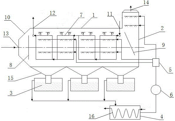
[0033] In order to overcome the problem that the thermal resistance of the heat exchange surface increases and the heat exchange efficiency gradually decreases due to tar condensation in the process of waste heat recovery, this embodiment provides a method such as figure 1 The shown coal pyrolysis gas cooling and waste heat recovery device includes an outer casing 10, a liquid seal tank 3, a separation pool 4, a controller 5 and a circulation pump 6; the outer casing 10 includes a connected horizontal casing 1 and Vertical shell 2; the horizontal shell 1 is provided with a cooling medium outlet 12 on the left side of the upper end, a cooling medium inlet 11 on the right side of the upper end, a pyrolysis gas inlet 13 on the left end, and inlet gas distribution plates 8 at both ends of the interior And the outlet gas distribution plate 9, a heat exchange body 7 is arranged in the middle of the interior, and a nozzle is arranged on the outside of the heat exchange body 7; a pyrol...

Embodiment 2

[0040] On the basis of embodiment 1, this embodiment provides a kind of figure 1 In the shown coal pyrolysis gas cooling and waste heat recovery device, in order to ensure that the pyrolysis gas is evenly distributed after entering the horizontal shell 1, the inlet gas distribution plate 8 and the outlet gas distribution plate 9 are provided with ventilation holes.

[0041] Further, the lower part of the outer casing 10 is provided with a cone bucket 15, and the conical cone bucket is conducive to collecting the liquid in the outer casing 10 and entering the liquid seal tank 3, so as to avoid splashing and causing pollution.

[0042] In addition, in order to reduce heat loss, the outer casing 10 is packaged with aluminum silicate or rock wool insulation material.

[0043] Furthermore, the separation pool 4 is provided with a cooling water pipe 16, the inlet of the cooling water pipe 16 is connected with cooling water, and the outlet of the cooling water pipe 16 discharges hot ...

Embodiment 3

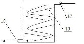
[0045] On the basis of embodiment 2, this embodiment provides a kind of figure 2 In the shown coal pyrolysis gas cooling and waste heat recovery device, the upper end of one side of the heat exchange body 7 is provided with a cooling medium inlet 17, and the lower end of the other side is a cooling medium outlet 18, and a guide is provided along the cooling medium flow direction. Flow plate 19. The cooling medium passes through the deflector 19 from the cooling medium inlet 17 to the cooling medium outlet 18, changing the flow direction and velocity of the medium, prolonging the residence time of the cooling medium in the passage, and enhancing the heat exchange capacity of the medium at the same time.

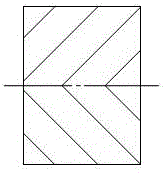
[0046] Such as image 3 As shown, the outer surfaces of both sides of the heat exchange body 7 are symmetrically distributed with cooling fins. On the one hand, the heat transfer area can be increased, and on the other hand, the air flow direction can be changed to disturb t...


PUM


Abstract

The invention provides a device for coal pyrolysis gas cooling and waste heat recovery. The device comprises an outer shell body, a liquid sealing trough, a separation pool, a controller and a circulating pump; the outer shell body comprises a horizontal shell body and a vertical shell body which communicates with each other, the left side of the upper end of the horizontal shell body is provided with a cooling medium outlet, and the right side of the upper end of the horizontal shell body is provided with a cooling medium inlet; the left end of the horizontal shell body is provided with a pyrolysis gas inlet, two ends of the interior of the horizontal shell body are provided with an inlet gas distribution plate and an outlet gas distribution plate respectively, the middle of the interior of the horizontal shell body is provided with a heat exchange body, and a spray pipe is arranged outside the heat exchange body; the upper end of the vertical shell body is provided with a pyrolysis gas outlet, and a spray pipe is arranged inside the vertical shell body; the spray pipe outside the heat exchange body and the spray pipe inside the vertical shell body are both connected to the controller through pipelines; the controller is connected to the separation pool through a circulating pump; the bottom of the outer shell body is connected with the liquid sealing trough; the liquid sealing trough is connected to the separation pool. The device has the advantages of simple structure and convenient operation, and solves the technical problems that increasing of heat resistance of a heat exchange surface and gradual reduction of the heat exchange efficiency are caused by tar condensation in a waste heat recovery process.

Description

technical field [0001] The invention belongs to the technical field of coal chemical industry, and in particular relates to a cooling and waste heat recovery device for pyrolysis gas in the coal pyrolysis process. Background technique [0002] When using a multi-heating tube rotary pyrolysis kiln or similar device for coal pyrolysis, the pyrolysis gas generated from the pyrolysis device usually has a temperature of 450-650 °C, and the sensible heat contained in it is still considerable. And in the discharged pyrolysis gas, similar to coke oven gas, usually contains tar gas. As the temperature decreases, the tar gradually condenses and precipitates out of the gas. In order to collect tar from the pyrolysis gas and maintain its high purity, the current preferred method is to first filter the pyrolysis gas at high temperature with a ceramic or metal-based filter tube filter, and then The gas is cooled, and the tar is condensed and precipitated in the process of continuously l...

Claims


Application Information

Patent Timeline
Patent Type & Authority Applications(China)
IPC IPC(8): C10K1/04F28F25/06F28F27/00F28G9/00
CPCC10K1/002C10K1/046F28F25/06F28F27/00F28G9/00Y02P20/10Y02P20/129
Inventor 赵玉良史剑鹏王高锋马玄恒李俊辉师浩浩
Owner CHINA NAT HEAVY MACHINERY RES INSTCO
Why Eureka
Try Eureka