Assembly structure of prefabricated concrete beam and concrete-filled steel tube column

A technology of concrete-filled steel tube columns and prefabricated concrete, which is applied in building construction and construction, and can solve the problems of steel beams that are prone to buckling, fire performance, large cross-sectional size of joint joints, and complicated binding and connection of steel bars, so as to improve the energy of joints Dissipative capacity, convenient and fast construction, reliable quality effect

Inactive Publication Date: 2016-07-20
FUJIAN UNIV OF TECH
View PDF9 Cites 18 Cited by
  • Summary
  • Abstract
  • Description
  • Claims
  • Application Information

AI Technical Summary

Problems solved by technology

[0003] Most of the joints of traditional reinforced concrete beams and steel pipe concrete columns are connected by steel bars around, and formwork needs to be installed on site, the binding and connection of steel bars are complicated, and the construction is difficult; the cross-sectional size of the joint joints is large
In the joint assembly structure of the steel pipe concrete column connection, it is mainly connected to the steel beam. The connection uses end plates and bolts, and is connected to the steel pipe outside the column. The steel beam is prone to buckling and has poor fire resistance
[0004] In the connection between precast concrete beams and reinforced concrete columns, the core part of the joint is mainly anchored by steel bars and then poured concrete. This method requires wet work on site, and the columns still need to be connected by sleeve grouting. The construction is troublesome and the quality is difficult to guarantee.

Method used


Image

  • Assembly structure of prefabricated concrete beam and concrete-filled steel tube column
  • Assembly structure of prefabricated concrete beam and concrete-filled steel tube column
  • Assembly structure of prefabricated concrete beam and concrete-filled steel tube column

Examples


Embodiment Construction

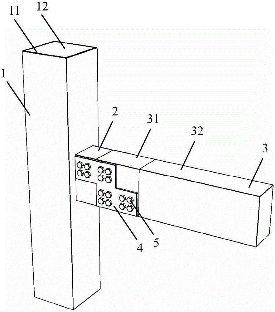
[0031] see Figure 1 to Figure 9 As shown, an assembly structure of precast concrete beams and steel tube concrete columns, including steel tube concrete columns 1, steel tube concrete corbels 2, precast concrete beams 3, and connecting plates 4;

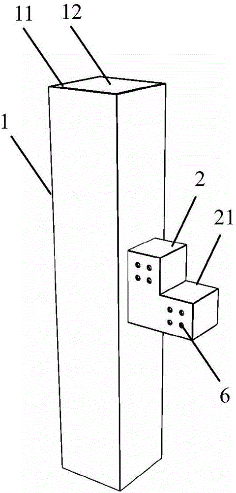
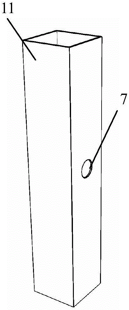
[0032] The steel pipe concrete column 1 is composed of a steel pipe column 11 and a concrete column 12 filled into the steel pipe column 11;

[0033] The side of the concrete-filled steel pipe column 1 is welded with a concrete-filled steel pipe corbel 2, and the concrete-filled steel pipe corbel 2 is stepped; the concrete-filled steel pipe corbel 2 includes corbel steel 21 and corbel concrete 22 filled inside the corbel steel 21; the corbel A plurality of tension bolt holes 6 are arranged on the side of the section steel 21;

[0034] The precast concrete beam 3 includes pre-embedded section steel 31 at the beam end and prefabricated reinforced concrete 32. The pre-embedded section steel 31 at the beam end is in the shape of an inv...


PUM


Abstract

The invention discloses an assembly structure of a prefabricated concrete beam and a concrete-filled steel tube column. The assembly structure comprises the concrete-filled steel tube column, a concrete-filled steel tube bracket, the prefabricated concrete beam, beam end pre-buried steel and a connection plate, wherein the concrete-filled steel tube bracket is welded with a side part of the concrete-filled steel tube column; the concrete-filled steel tube bracket is step-shaped; the concrete-filled steel tube bracket comprises bracket-shaped steel and bracket concrete filled in the bracket-shaped steel; a plurality of opposite-pull bolt holes are formed in the side surface of the bracket-shaped steel; the prefabricated concrete beam comprises the beam end pre-buried steel and prefabricated reinforced concrete; the beam end pre-buried steel is step-shaped and is matched with the shape of the concrete-filled steel tube bracket; a plurality of opposite-pull bolt holes are also formed in the side surface of the beam end pre-buried steel; the connection plate is arranged on the side surface of the bracket-shaped steel and the beam end pre-buried steel and is locked and fastened by a plurality of opposite-pull bolts. The assembly structure of the prefabricated concrete beam and the concrete-filled steel tube column is high in bearing capacity, high in earthquake-resistant ductility, high in node energy dissipation capacity, convenient to construct and high in construction quality, and can provide effective restraint on the concrete.

Description

【Technical field】 [0001] The invention belongs to the technical field of prefabricated assembled structures in civil engineering, and in particular relates to an assembled structure of prefabricated concrete beams and steel pipe concrete columns. 【Background technique】 [0002] The traditional cast-in-place construction method has a low degree of industrialization, poor construction conditions, time-consuming and labor-intensive, is not conducive to energy conservation and environmental protection, common quality problems are difficult to eradicate, and safety accidents also occur from time to time. The use of prefabricated structures can save energy, water, and materials, greatly reduce construction waste, reduce noise pollution, reduce labor consumption and intensity, effectively improve the construction environment, and improve project quality. [0003] Most of the joints of traditional reinforced concrete beams and concrete-filled steel tube columns are connected by stee...

Claims


Application Information

Patent Timeline
Patent Type & Authority Applications(China)
IPC IPC(8): E04B1/21
CPCE04B1/21E04B1/215
Inventor 郑永乾郑莲琼庄金平颜桂云张铮
Owner FUJIAN UNIV OF TECH
Why Eureka
Try Eureka