Multi-cavity hydraulic cylinder and control system and method thereof

A technology for controlling systems and body fluids, applied in fluid pressure actuating devices, servo motors, mechanical equipment, etc., can solve problems such as low efficiency of hydraulic systems, and achieve the effect of improving efficiency, promoting practicality, and improving load capacity

Active Publication Date: 2016-07-20
NAT UNIV OF DEFENSE TECH
View PDF9 Cites 5 Cited by
  • Summary
  • Abstract
  • Description
  • Claims
  • Application Information

AI Technical Summary

Problems solved by technology

[0008] The purpose of the present invention is to solve the problem of low efficiency of the existing single-pump source-multi-actuator hydraulic system by providing a multi-cavity design of the hydraulic cylinder, and selecting different cavities to conduct with the high-p...

Method used


Image

  • Multi-cavity hydraulic cylinder and control system and method thereof
  • Multi-cavity hydraulic cylinder and control system and method thereof
  • Multi-cavity hydraulic cylinder and control system and method thereof

Examples


Embodiment Construction

[0042] Below in conjunction with accompanying drawing, the specific implementation manner of this patent is described in further detail.

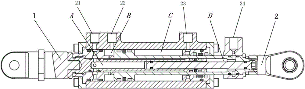
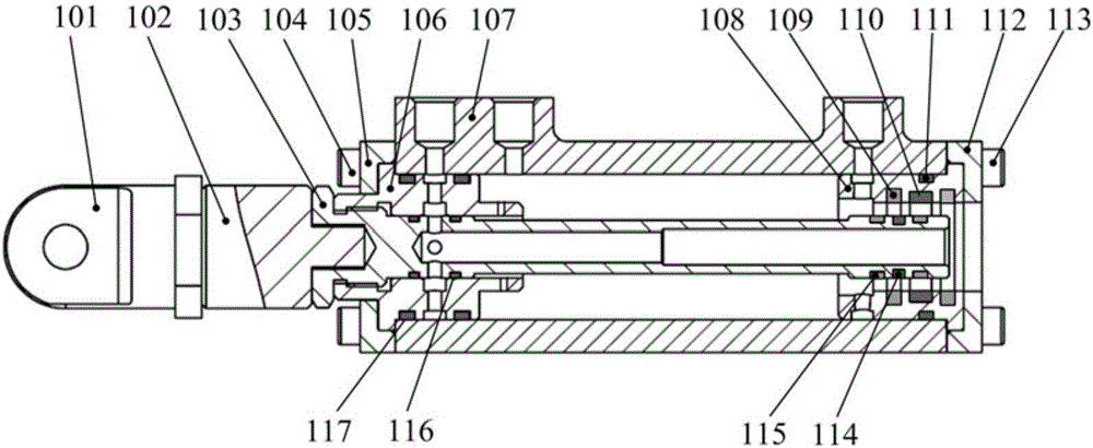
[0043] As shown in Figure 1(a), the multi-cavity hydraulic cylinder is composed of a composite cylinder 1 and a composite piston rod 2, forming a first cavity A, a second cavity B, a third cavity C and a fourth cavity Cavity D. As shown in Figure 1(b), the composite cylinder 1 includes an end ring 101, a pressure sensor 102, an inner cylinder 103 (including the right piston ring), a connecting screw 104, an end cover 105, a sealing sleeve 106, and a piston at the right end of the inner cylinder. Ring dynamic sealing ring 114, inner cylinder right end piston ring guide ring 115, first static sealing ring 116, second static sealing ring 117, outer cylinder 107, sealing sleeve 108, guide ring 109, dynamic sealing ring 110, second Three static sealing rings 111, end caps 112, and connecting screws 113. Wherein the end ring 101, the pressure s...


PUM


Abstract

Disclosed is a multi-cavity hydraulic cylinder. The multi-cavity hydraulic cylinder comprises a combined cylinder barrel and a combined piston rod. The cylinder barrel and the piston rod form four enclosed cavities A, B, C and D. According to a hydraulic cylinder control system and method, the system comprises four plug-in type two-position three-way electromagnetic switch valves connected with the four cavities of the multi-cavity hydraulic cylinder and a proportional throttle valve connected with four electromagnetic switch valves. By controlling the two-position three-way electromagnetic switch valves and a three-position four-way servo valve which is the proportional throttle valve, whether the four enclosed cavities A, B, C and D communicate with an oil outlet P and an oil tank oil return port T of a pump or not can be selected, and therefore, different effective action areas are obtained. A carrying capacity sensor is arranged on the piston rod and used for measuring loads on the piston rod in real time, that is to say, loads of the multi-cavity hydraulic cylinder. According to load feedback, through control over the group of electromagnetic switch valves and a servo valve group, the appropriate effective action areas are selected, match of the maximum output force and the carrying capacity of the hydraulic cylinder is achieved, and finally, high-precision position or force control is achieved through a proportional throttle function of the servo valve.

Description

technical field [0001] The invention relates to a multi-cavity hydraulic cylinder, a control system and a control method thereof. Background technique [0002] The limited load capacity has become a "bottleneck" problem that restricts the practical application of mobile robots. It is currently a common method used by robot research institutions in the world to use high-power-density hydraulic drive to improve the load capacity of mobile robots. For example, BIGDOG and petman developed by Boston Dynamics , the KenKen II hydraulically driven quadruped robot of the Italian Polytechnic University, and the high-performance quadruped robot project funded by China's 863 High Technology Research and Development Program clearly proposes to use a hydraulic drive system. [0003] Due to weight and volume limitations, the hydraulic drive system of mobile robots adopts a single-pump source-multi-actuator system structure, such as the literature "Design and control of ranger: Anenergy-eff...

Claims


Application Information

Patent Timeline
IPC IPC(8): F15B15/16F15B11/08
CPCF15B11/08F15B15/16
Inventor 杨军宏王卓薛勇尚建忠徐小军罗自荣
Owner NAT UNIV OF DEFENSE TECH
Why Eureka
Try Eureka