Power inductor core with closed magnetic circuit structure

A power inductor and closed magnetic circuit technology, applied in the field of inductors, can solve the problem that power inductor cores are difficult to achieve low power consumption, high power, simultaneous matching of production automation, poor performance of anti-EMI electromagnetic interference, and magnetic cores. It is unfavorable for mass production and use, and achieves the effects of stable inductance, improved EMI performance, and maximum power transmission

Inactive Publication Date: 2016-07-20
DADONG ELECTRONICS
View PDF9 Cites 0 Cited by
  • Summary
  • Abstract
  • Description
  • Claims
  • Application Information

AI Technical Summary

Problems solved by technology

[0003] At present, the magnetic core of the power inductor adopts the structure of the I-shaped magnetic core, which is combined with the magnetic ring (such as Figure 1A-1D As shown), the shielding effect is not good, the performance of anti-EMI electromagnetic interference is poor, and the magnetic flux leakage is large
To achieve the minimum power consumption coefficient and maximum power transmission, the structural design of the magnetic core must require high precision and good coordination, which increases the complexity of the production of the magnetic core and makes the magnetic core unfavorable for mass production and Use, bring greater trouble to production
[0004] At present, it is difficult to achieve the simultaneous matching of low power consumption, high power and production automation in the design of power inductor cores

Method used


Image

  • Power inductor core with closed magnetic circuit structure
  • Power inductor core with closed magnetic circuit structure
  • Power inductor core with closed magnetic circuit structure

Examples


Embodiment 1

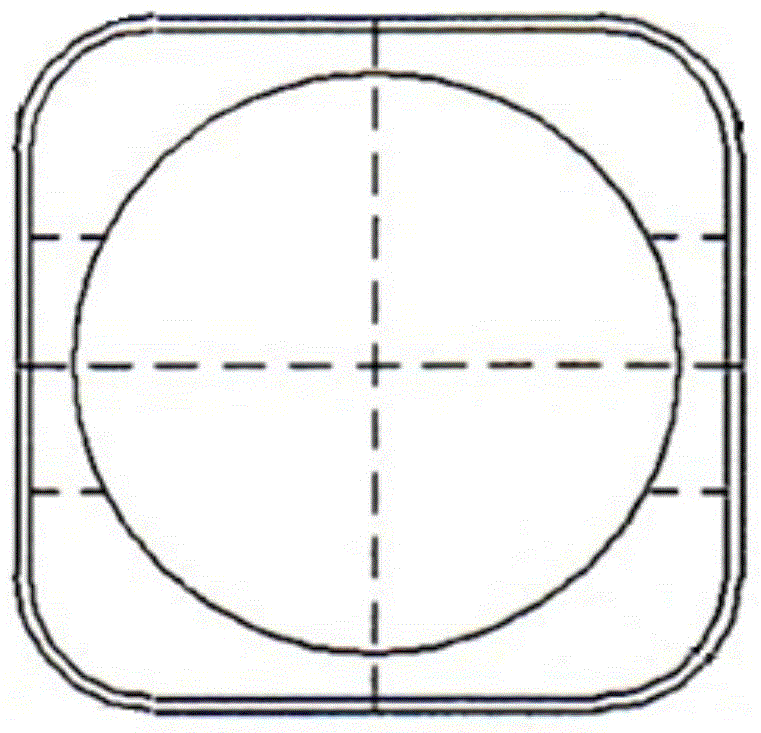
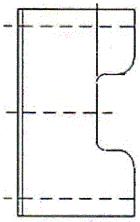
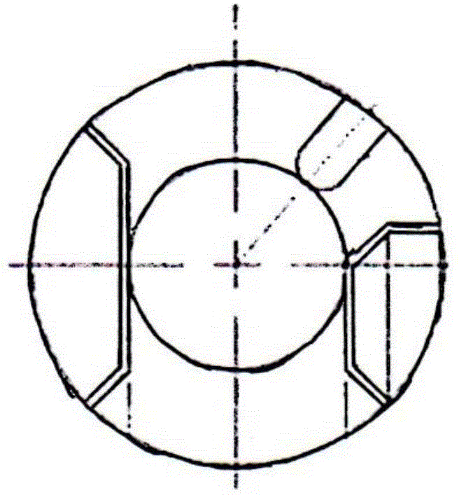
[0038] Such as Figure 2A-2C , 3A~3B and Figure 4 As shown, the magnetic core of the power inductor with the closed magnetic circuit structure of the present invention has a magnetic base 1 and a magnetic cover 2, the magnetic cover 2 is fastened on the magnetic base 1, and the central part of the magnetic base 1 is a magnetic core 3 integrated with the magnetic base , The periphery of the magnetic core 3 is a groove 4 for placing the coil.

[0039] The side of the groove 4 is provided with a notch 5 for leading out the coil wiring, and a notch 6 for installing a terminal is reserved at a position corresponding to the notch 5 on the magnetic cover 2 .

[0040] In this embodiment, the notch 6 reserved for installing the terminal is to form an electrode after the terminal and the outgoing wire are combined, so that the coil outgoing wire is connected to the terminal to facilitate welding.

[0041] The present invention uses the combined structure of the magnetic base 1 and th...

Embodiment 2

[0046] Such as Figures 5A-5B , 6A~6C and Figure 7 As shown, in order to further reduce the volume and realize the miniaturization of products, the present invention also has a second structure.

[0047] The difference between this embodiment and Embodiment 1 is that it has a magnetic base 1 and a magnetic cover 2, the magnetic cover 2 is fastened on the magnetic base 1, the magnetic base 1 is T-shaped when viewed from the side, and the central part of the magnetic base 1 protrudes It is the magnetic core 3 integrated with the magnetic base 1 .

[0048] In this embodiment, a pair of sides of the magnetic base 1 is wrapped inside the magnetic cover 2, that is, a pair of sides of the magnetic cover 2 are combined with the edge of the magnetic base 1, and the other pair of sides of the magnetic cover is provided with an outgoing line. Groove, this structure can facilitate the production process and improve production efficiency.

[0049] A pair of edge portions where the magn...


PUM


Abstract

The invention relates to a power inductor core with a closed magnetic circuit structure. The power inductor core comprises a magnetic base and a magnetic cover, wherein the magnetic cover is fastened to the magnetic base; a magnetic core integrated with the magnetic base is arranged at the center part of the magnetic base; a groove for placing a coil is formed in the periphery of the magnetic core; notches for leading out a coil connector are formed in the edge parts of the groove; and gaps for installing a terminal are reserved at the parts, corresponding to the notches, of the magnetic cover. The invention provides a low-loss and high-current Ni-Zn ferrite core applied to a design of a power inductor product; the design of the low-loss power inductor is achieved; and the product achieves simultaneous matching of low loss, high power and production automation.

Description

technical field [0001] The invention relates to an inductor, in particular to a power inductor magnetic core with a closed magnetic circuit structure. Background technique [0002] In the application field of electronic power inductor products, power inductor products require large current and low power consumption, which requires the magnetic core saturation induction (Bs) of power inductors to be as large as possible. Moreover, power inductor products must also have sufficient characteristics to prevent interference with other surrounding electronic components, and have less magnetic leakage outflow. In addition, under the current trend of competition in the electronic product market, the production of products is required to be transformed to automation as much as possible to achieve miniaturization, low energy consumption, and low-cost production methods. [0003] At present, the magnetic core of the power inductor adopts the structure of the I-shaped magnetic core, whi...

Claims


Application Information

Patent Timeline
Patent Type & Authority Applications(China)
IPC IPC(8): H01F27/24H01F27/26
Inventor 刘竞强李彦辉张刚
Owner DADONG ELECTRONICS
Why Eureka
Try Eureka