High-frequency electrical wire and coil

A high-frequency and wire technology, applied in the field of high-frequency wires and coils, can solve problems such as difficulty in reducing AC resistance

Inactive Publication Date: 2016-07-20
FUJIKURA LTD
View PDF14 Cites 2 Cited by
  • Summary
  • Abstract
  • Description
  • Claims
  • Application Information

AI Technical Summary

Problems solved by technology

However, in copper-clad aluminum wires, it is difficult to reduce the AC resistance compared with copper wires of the same wire diameter

Method used


Image

  • High-frequency electrical wire and coil
  • High-frequency electrical wire and coil
  • High-frequency electrical wire and coil

Examples


Embodiment 1~3、 comparative example 1

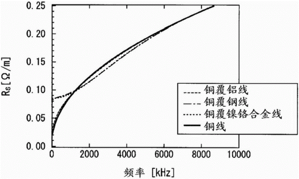
[0155] For the two-layer structure conductor (copper-clad aluminum wire) whose inner layer is formed by alloy aluminum wire and outer layer is formed by copper (embodiment 1), the inner layer is formed by steel wire and the outer layer is formed by copper Steel-clad wire) (Example 2), and a two-layer structure conductor (copper-clad Ni-Cr alloy wire) (Example 3) in which the inner layer is made of nickel-chromium alloy wire and the outer layer is made of copper (Example 3), the following calculations were carried out.

[0156] For comparison, the same calculation was performed for a copper wire having a single-layer structure (one-layer structure) (Comparative Example 1). The copper wire may be circular in cross section. A single-layer structure refers to a structure composed of a homogeneous material.

[0157] In the following description, a two-layer structure conductor or a copper wire may be simply referred to as a "wire". In addition, alloy aluminum may be simply referr...

Embodiment 3

[0171] In Example 3 (copper-coated nickel-chromium alloy wire), compared with Comparative Example 1 (copper wire), the maximum resistance R s about 7% lower.

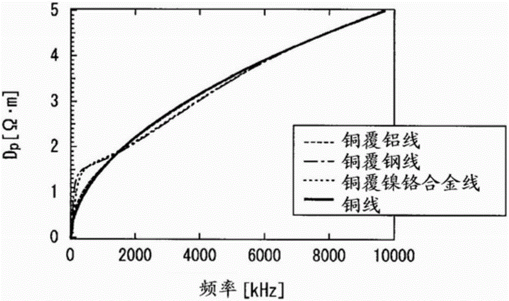
[0172] Figure 5 is for easy understanding figure 2 The calculation results shown represent the D of Examples 1-3 and Comparative Example 1 (copper wire). pThe graph of the ratio (Examples 1-3 / Comparative Example 1). From this figure, the following situation can be seen.

[0173] In Example 1 (copper-clad aluminum wire), with respect to Comparative Example 1 (copper wire), the maximum D p about 1% lower.

[0174] In Example 2 (copper-clad steel wire), with respect to Comparative Example 1 (copper wire), the maximum D p about 7% lower.

[0175] In Example 3 (copper-coated nickel-chromium alloy wire), with respect to Comparative Example 1 (copper wire), the maximum D p about 7% lower.

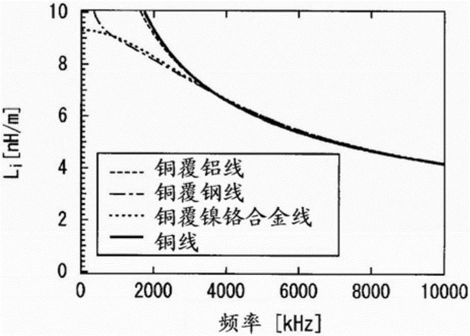
[0176] Figure 6 is for easy understanding image 3 The calculation results shown show the internal inductance L of Examples ...

Embodiment 4

[0181] For the two-layer structure conductor (copper-clad steel wire) that was the same as in Example 2 except that the cross-sectional area ratio of the outer layer was set to 75%, the R relative to Comparative Example 1 (copper wire) was obtained. s Ratio, D p ratio, and L i Ratio. The result is as Figure 7A shown.

[0182] exist Figure 7A In, relative to the R of Comparative Example 1 (copper wire) s The ratio is recorded as "R s (75%CS / Cu)", the D p The ratio is recorded as "D p (75%CS / Cu)", the L i The ratio is recorded as "L i (75% CS / Cu)".


PUM

PropertyMeasurementUnit
electrical resistivityaaaaaaaaaa

Abstract

This high-frequency electrical wire has a conductor section provided with an inner layer formed from a material having a lower conductivity than copper, and an outer layer formed from copper and covering the inner layer. In the frequency range of AC current for which the high-frequency electrical wire is used, when the skin thickness (delta [m]) of a copper wire provided with the conductor section and comprising pure copper is stipulated to be delta=[square root of](2 / [delta][sigma][mu]), the outer layer thickness (t (m)) satisfies 1.1[delta]<t< 2.7[delta]. Here, [omega] is the angular frequency of the current represented by 2[pi]f, [mu] is the magnetic permeability (H / m) of the copper wire, [sigma] is the conductivity ([omega]-1m-1) of the copper wire, and f is frequency (Hz).

Description

technical field [0001] The present invention relates to high-frequency electric wires and coils, for example, to high-frequency electric wires and coils used for windings and cables of various high-frequency devices. [0002] This application claims priority based on Japanese Patent Application No. 2013-249685 for which it applied in Japan on December 2, 2013, and uses the content here. Background technique [0003] In windings and cables of equipment through which alternating current flows, eddy currents are generated in conductors by the magnetic field generated by the alternating current. As a result, the AC resistance increases due to the skin effect and the proximity effect, which may cause heat generation and increase power consumption. [0004] As countermeasures for suppressing the skin effect and the proximity effect, there are reductions in the diameter of the element wires and the use of twisted wires in which each element wire is insulated and covered (see Paten...

Claims


Application Information

Patent Timeline
Patent Type & Authority Applications(China)
IPC IPC(8): H01B5/02H01B7/00H01B7/30H01F5/00H01F5/06H01F27/28
CPCH01F5/00H01B7/30H01F27/2823H01B5/02H01B7/02H01B7/17H01F5/06H01B7/0009
Inventor 上泷千寻官宁满野隆史
Owner FUJIKURA LTD
Why Eureka
Try Eureka