Speed reducer, differential drive device, robot and mechanical arm
A technology of differential drive and reducer, which is applied in the direction of transmission, gear transmission, multi-ratio transmission, etc., which can solve problems such as fatigue damage, small transmission ratio of reducer, and input torque that cannot meet the requirements, so as to reduce loss Effect
- Summary
- Abstract
- Description
- Claims
- Application Information
AI Technical Summary
Problems solved by technology
Method used
Image
Examples
Embodiment 1
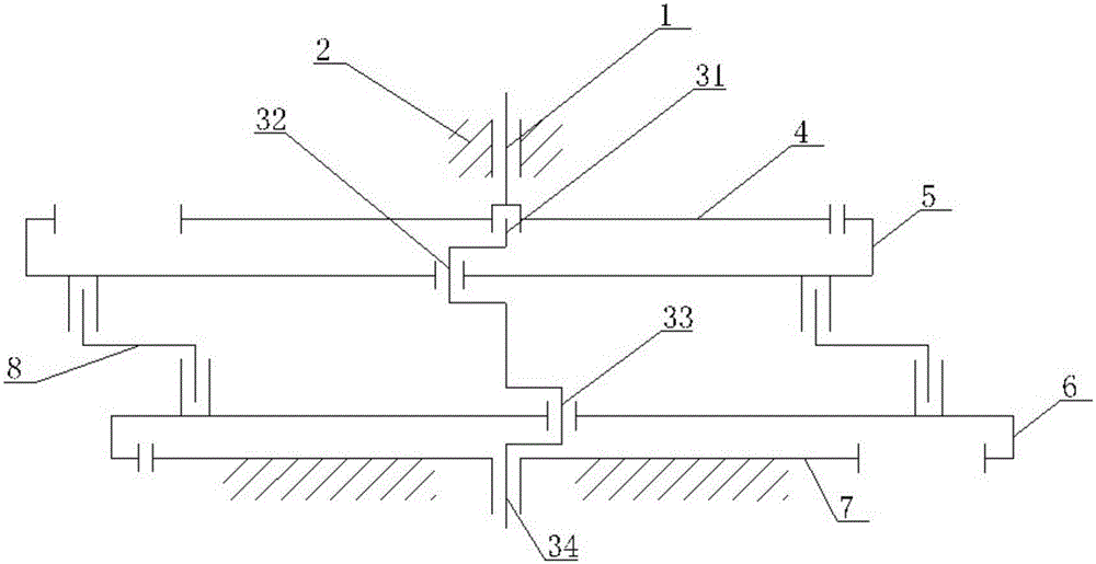
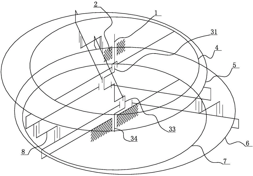
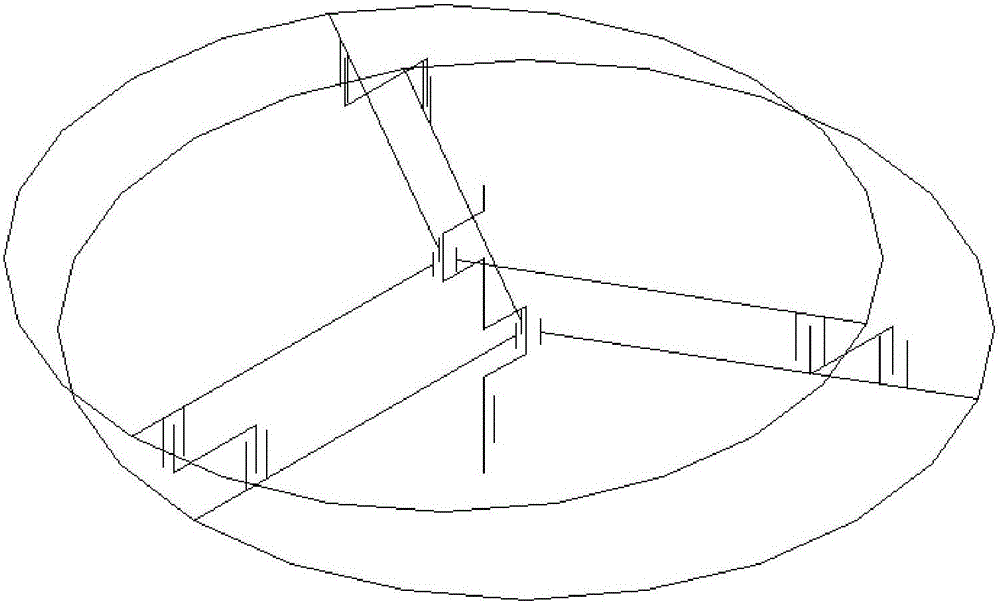
[0049] figure 1 It is the structural representation of the reducer of embodiment 1: figure 2 yes figure 1 The three-dimensional structural schematic diagram of the reducer; image 3 yes figure 2 Simplified schematic of the intermediate transmission section shown.
[0050] In the figure, the meanings of each reference sign are as follows: 1. output shaft; 2. housing; 31. connecting section of output shaft; 32. second crank; 33. first crank; 34. input section; The second sun gear; 5. The second planetary ring gear;
[0051] 6. The first planetary ring gear; 7. The first sun gear; 8. The connecting rod of the eccentric coupling.
[0052]A speed reducer, comprising an output shaft 1, the output shaft 1 is rollingly mounted on a housing 2, the output shaft 1 is fixed with a second sun gear 4 in a relatively circumferential manner, and the second sun gear 4 is connected to the second planetary internal gear The second planetary ring gear 5 is connected to the first planetary...
Embodiment 2
[0060] Figure 4 It is the structural representation of embodiment 2;
[0061] In the drawings used in this embodiment, the same reference signs as those used in the above embodiments still follow the definition of the reference signs in the drawings used in the above embodiments.
[0062] The difference between this embodiment and the embodiment is that both the output shaft 1 and the input shaft are hollow shafts.
[0063] Both the output shaft 1 and the input shaft are set as hollow shafts, which not only saves materials, but also uses larger bearings to bear the rotational load, which improves the strength of the system, and also frees up the space inside the shaft for wires to pass through , which is particularly advantageous when the reducer is used in the field of robots and manipulators.
Embodiment 3
[0065] Figure 5 It is a three-dimensional schematic diagram of the intermediate transmission part in the reducer of embodiment 3;
[0066] The three eccentric coupling rods 8 (in the figure, only one eccentric connecting rod is shown) have the same eccentric rod length, which is different from the eccentricity of the first crank throw and the second crank throw. The connection between the eccentric shaft coupling and the first planetary ring gear and the second planetary ring gear are respectively at the same distance from the axis of each planetary ring gear.
[0067] By setting different eccentricities, it is possible to avoid the connection line between the axis of the first crankshaft and the axis of the second crankshaft, and the connection axis of the connecting rod of the eccentric coupling and the first planetary ring gear and the axis of the first crankshaft , the line connecting the two axes of the eccentric connecting rod, the connecting axis connecting the eccent...
PUM
 Abstract
Description
Claims
Application Information
 - R&D
- Intellectual Property
- Life Sciences
- Materials
- Tech Scout
- Unparalleled Data Quality
- Higher Quality Content
- 60% Fewer Hallucinations
Browse by: Latest US Patents, China's latest patents, Technical Efficacy Thesaurus, Application Domain, Technology Topic, Popular Technical Reports.
© 2025 PatSnap. All rights reserved.Legal|Privacy policy|Modern Slavery Act Transparency Statement|Sitemap|About US| Contact US: help@patsnap.com


