Mid-infrared electro-optical modulator based on black phosphorus fluoride waveguide

An electro-optic modulator and fluoride technology, which is applied in the field of optical communication, can solve the problems that mid-infrared light cannot pass through, achieve the effect of flat mid-infrared spectrum transmission window, convenient manufacture, and favorable integration

Inactive Publication Date: 2016-07-27
UNIV OF ELECTRONICS SCI & TECH OF CHINA
View PDF3 Cites 5 Cited by
  • Summary
  • Abstract
  • Description
  • Claims
  • Application Information

AI Technical Summary

Problems solved by technology

However, when the mid-infrared light is modulated by a modulator made of lithium niobate material, the mid-infrared light cannot pass throu

Method used


Image

  • Mid-infrared electro-optical modulator based on black phosphorus fluoride waveguide
  • Mid-infrared electro-optical modulator based on black phosphorus fluoride waveguide
  • Mid-infrared electro-optical modulator based on black phosphorus fluoride waveguide

Examples


Embodiment 1

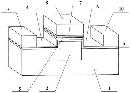
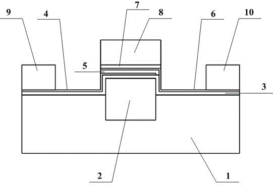
[0034] A mid-infrared electro-optic modulator based on black phosphorus fluoride waveguide, comprising a substrate layer 1, a groove is opened on the upper surface of the substrate layer 1, a first optical waveguide 2 is arranged in the groove, and the first optical waveguide 2 is arranged in the groove. On the upper surface of an optical waveguide 2, a first isolation dielectric layer 3, a first black phosphorus layer 4, a second isolation dielectric layer 5, a second black phosphorus layer 6, and a third isolation dielectric layer 7 are sequentially stacked from bottom to top. , the upper surface of the third isolation dielectric layer 7 is provided with a second optical waveguide 8, the first black phosphorus layer 4 extends from the left side of the first optical waveguide 2 and is connected to the first electrode 9, the second The black phosphorus layer 6 extends from the right side of the first optical waveguide 2 and is connected to the second electrode 10; the materials...

Embodiment 2

[0036] Based on the first embodiment, the fluoride glass is fluorozirconate glass or fluoroaluminate glass.

Embodiment 3

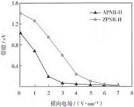
[0038] On the basis of Embodiment 1 or Embodiment 2, the materials of the first black phosphorus layer 4 and the second black phosphorus layer 6 are passivated black phosphorus nanobelts.

[0039] Preferably, the passivated black phosphorus nanobelts are hydrogen-saturated passivated black phosphorus nanobelts or fluorine-saturated passivated black phosphorus nanobelts.


PUM


Abstract

The invention discloses a mid-infrared electro-optical modulator based on a black phosphorus fluoride waveguide, belongs to a mid-infrared electro-optical modulator in the field of optical communication, and aims to provide the mid-infrared electro-optical modulator based on the black phosphorus fluoride waveguide. Fluoride glass is used as a waveguide material, so that a modulation rate of the mid-infrared electro-optical modulator is effectively improved. The invention adopts the technical scheme that the mid-infrared electro-optical modulator comprises a substrate layer; a groove is formed on the upper surface of the substrate layer; a first optical waveguide is arranged in the groove; a first isolation dielectric layer, a first black phosphorus layer, a second isolation dielectric layer, a second black phosphorus layer and a third isolation dielectric layer are sequentially laminated on the upper surface of the first optical waveguide from bottom to top; a second optical waveguide is arranged on the upper surface of the third isolation dielectric layer; the first black phosphorus layer extends out of the left side of the first optical waveguide and is connected with a first electrode; the second black phosphorus layer extends out of the right side of the first optical waveguide and is connected with a second electrode. The invention is applicable to the mid-infrared electro-optical modulator.

Description

technical field [0001] The invention belongs to the field of optical communication and relates to a mid-infrared electro-optic modulator. Background technique [0002] As the basis and key components of optical communication systems, optical modulators have always been a hotspot in the research of integrated optics. Its function is to change the intensity, phase, polarization and other characteristics of the optical carrier passing through the optical modulator, and load the electrical signal on the optical carrier. In recent years, the development of integrated optical devices, especially silicon-based integrated optoelectronic devices, has been very rapid, and various new optical devices have been reported continuously. They have low production costs, high performance reliability, and can be combined with circuit systems to form multifunctional The optoelectronic hybrid module and system will be widely used in communication, sensing, military, biology and many other field...

Claims


Application Information

Patent Timeline
IPC IPC(8): G02F1/035
CPCG02F1/035
Inventor 陆荣国田朝辉叶胜威刘天良陈德军张尚剑刘永
Owner UNIV OF ELECTRONICS SCI & TECH OF CHINA
Why Eureka
Try Eureka