
Intelligent DC power distribution center-based urban distribution network grid structure

A technology of DC power distribution and grid structure, which is applied in the directions of AC network circuit, power transmission AC network, emergency treatment AC circuit layout, etc., and can solve the three-phase imbalance of the distribution network, reliability improvement and rapid recovery of the distribution network Anti-interference ability, the grid structure of urban distribution network can not adapt to the complex power system and other problems, to achieve the effect of simple structure and strong anti-interference ability

Active Publication Date: 2016-07-27
GUIZHOU UNIV
View PDF2 Cites 25 Cited by
  • Summary
  • Abstract
  • Description
  • Claims
  • Application Information

AI Technical Summary

Problems solved by technology

[0004] The technical problem to be solved by the present invention is to provide an urban distribution network grid structure based on an intelligent DC power distribution center to solve the problem that the existing urban distribution network grid structure cannot In terms of performance improvement, adjustment and control of power flow, distributed power access, etc., the distribution network cannot be quickly restored after a system failure and has strong anti-interference ability; it cannot effectively adjust and control the flow direction of the distribution network; it cannot After the distributed power supply is connected, it can realize the active suppression of three-phase unbalance and harmonic problems in the distribution network, etc.

Method used


Image

  • Intelligent DC power distribution center-based urban distribution network grid structure
  • Intelligent DC power distribution center-based urban distribution network grid structure
  • Intelligent DC power distribution center-based urban distribution network grid structure

Examples


Embodiment 1

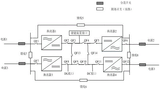
[0028] Embodiment 1: This embodiment mainly includes two sets of 10kV back-to-back multi-terminal DC power distribution systems (see figure 1 ), feeder lines 5, 6, 7, 8 with tie switches, DG interface, energy storage device interface, DC interface, circuit breakers QF1 to QF12 for controlling line disconnection; bidirectional converters 1 and 2 shown, bidirectional commutation Devices 3 and 4 constitute two groups of 10kV back-to-back multi-terminal DC power distribution systems respectively. The feeders 5, 6, 7, and 8 with tie switches are connected to the "intelligent DC power distribution center" through the AC side switches QF1, QF6, QF7, and QF12 of the bidirectional converter; The DG interface, the energy storage device interface, and the DC interface are respectively connected to the positive and negative DC busbars between the two converters of the 10kV back-to-back multi-terminal DC power distribution system.

[0029]The 10kV back-to-back multi-terminal DC power dist...

Embodiment 2

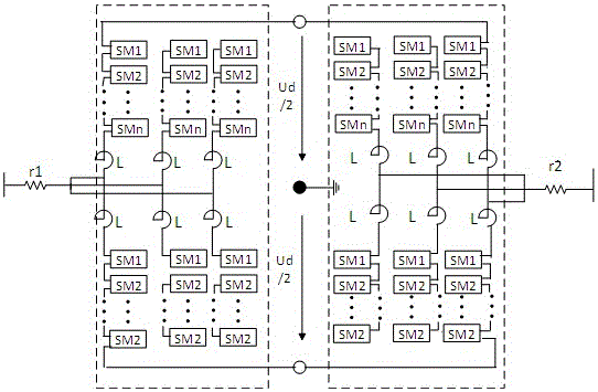
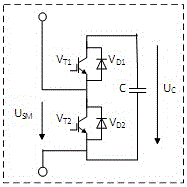
[0032] Example 2: figure 2 and image 3 It is a schematic diagram of the topological structure of the 10kV back-to-back multi-terminal DC power distribution system using the MMC structure of the present invention. The system consists of back-to-back converters at both ends and a DC line. Both the sending and receiving converters use MMC topology, and the two converters have the same structure.

[0033] The topology is a full-bridge type, each MMC has 6 bridge arms, and each bridge arm is composed of n sub-modules SM of the same specification and 1 reactance L connected in series. A single SM consists of 2 IGBTs corresponding to the figure and and a DC storage capacitor C, , is an antiparallel diode, is the SM capacitor voltage, is the output voltage of SM during steady state operation. The 10kV back-to-back multi-terminal DC power distribution system with MMC structure is easy to realize the reversal of power flow. In the reverse transmission of power, the flow...

Embodiment 3

[0035] If a fault occurs on the positive and negative DC bus between rooms 1 and 2 or between rooms 3 and 4 of bidirectional converters, the circuit breakers QF4 and QF9 will cut this part out, and the distribution network will be decomposed into two ring network structures with bidirectional converters. At this time, the two-way control of the power flow of the distribution network can still be realized;

[0036] If a side converter, converter 1, 3 or converter 2, 4 fails, the circuit breaker QF1, QF7 or QF6, QF12 will cut out the faulty part, and the distribution network will be decomposed into two parts, one part is the same as the existing one. The distribution grid structure of the ring network cannot control the power flow at this time; the other part is the distribution network grid structure connected with a bidirectional converter, which can realize bidirectional regulation of the power flow.

[0037] Converters on both sides, converters 1, 2, 3, and 4 all fail and st...


PUM


Abstract

The invention discloses an intelligent DC power distribution center-based urban distribution network grid structure, which comprises more than two groups of 10KV back-to-back multi-terminal DC power distribution systems, wherein each 10KV back-to-back multi-terminal DC power distribution system comprises an AC / DC converter and a DC / AC converter; four shutdown switches are connected between the AC / DC converter and the DC / AC converter in series; adjacent 10KV back-to-back multi-terminal DC power distribution systems are connected with each other through a sixth shutdown switch and a seventh shutdown switch; the sixth shutdown switch is connected between output ends of the first shutdown switches of the adjacent 10KV back-to-back multi-terminal DC power distribution systems; the seventh shutdown switch is connected between the output ends of the third shutdown switches of the adjacent 10KV back-to-back multi-terminal DC power distribution systems; and the input ends of the converters are connected through four groups of feeders connected with interconnection switches to form the grid structure. The technical problem that the prior art cannot adapt to a complicated power system, and especially the technical problems in the aspects of reliability improvement, control power flow adjustment, distributed power supply connection and the like are solved.

Description

technical field [0001] The invention relates to the field of power electronics and power system application technology, in particular to an urban distribution network grid structure based on an intelligent DC power distribution center. Background technique [0002] At present, the structural transformation of urban distribution network has become one of the hot topics concerned by the state, power grid companies and scholars. In the existing urban distribution network, whether it is a single ring network, multi-segment multi-connection, or N supply and one backup power supply mode, but in actual operation, the connection switch between feeders is disconnected, that is, "closed loop Wiring, open-loop operation", its essence is still a single power supply, and the power flow of the 10kV feeder line is uncontrollable. When an electrical fault occurs, the distribution network needs to cut off the fault through a section switch, and then close the tie switch to supply power. In ...

Claims


Application Information

Patent Timeline
IPC IPC(8): H02J3/36H02J3/06H02J3/38
CPCH02J3/001H02J3/06H02J3/36H02J3/381Y02E60/60
Inventor 袁旭峰常成
Owner GUIZHOU UNIV
Learn More