Batch type photocatalytic energy collection reactor and method for wastewater treatment by same

A technology for energy collection and wastewater treatment, applied in chemical instruments and methods, special compound water treatment, light water/sewage treatment, etc. Simple structure, saving floor space, and increasing the effect of degradation degree and speed

Active Publication Date: 2016-08-10
HARBIN INST OF TECH
View PDF3 Cites 3 Cited by
  • Summary
  • Abstract
  • Description
  • Claims
  • Application Information

AI Technical Summary

Problems solved by technology

[0005] The present invention aims to solve the problems of low efficiency of photocatalytic degradation of organic matter and poor use of chemical energy in the existing photocatalytic treatment of wastewater, and provides a batch-type photocatalytic energy collection reactor and a method of using it to treat wastewater

Method used


Image

  • Batch type photocatalytic energy collection reactor and method for wastewater treatment by same
  • Batch type photocatalytic energy collection reactor and method for wastewater treatment by same
  • Batch type photocatalytic energy collection reactor and method for wastewater treatment by same

Examples


specific Embodiment approach 1

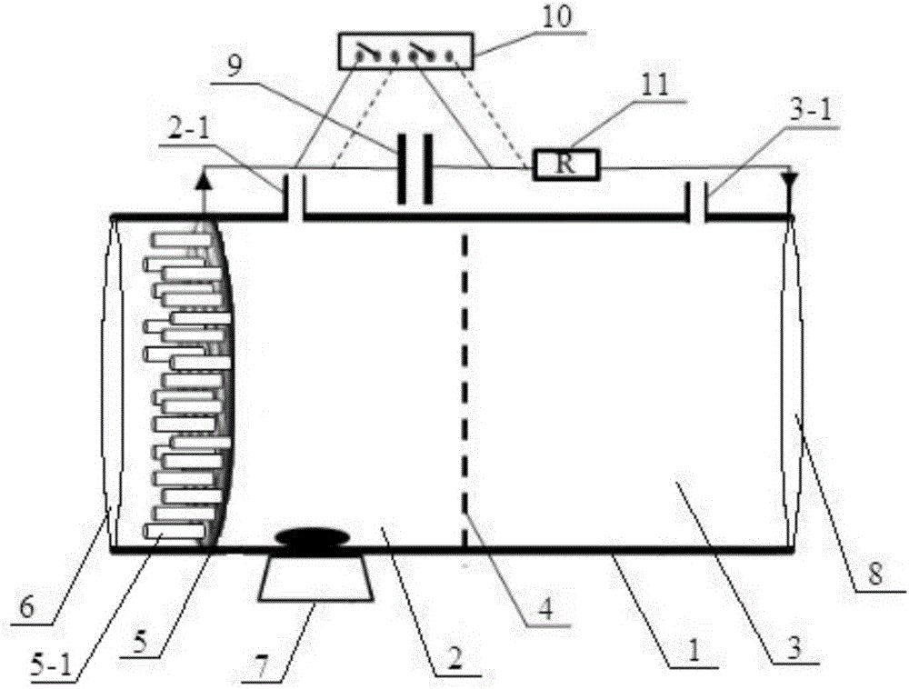
[0027] Specific implementation mode one: combine figure 1 Describe this embodiment, the intermittent photocatalytic energy harvesting reactor of this embodiment comprises housing 1, anode chamber 2, cathode chamber 3, proton exchange membrane 4, photoanode 5, quartz glass 6, stirring device 7, counter electrode 8, capacitor 9 and converter 10,

[0028] A proton exchange membrane 4 is provided in the middle of the housing 1, and the proton exchange membrane 4 divides the inner chamber of the housing 1 into an anode chamber 2 and a cathode chamber 3, and a photoanode 5 is provided on the housing 1 at one end of the anode chamber 2, and the housing 1 The upper end of the cathode chamber 3 is provided with a counter electrode 8, the photoanode 5 is covered with quartz glass 6, the inner bottom of the anode chamber 2 is provided with a stirring device 7, and the housing 1 is located on the side of the anode chamber 2. An anode chamber water inlet 2- 1. On the side of the cathode c...

specific Embodiment approach 2

[0029] Embodiment 2: This embodiment is different from Embodiment 1 in that: the housing 1 is a flat cylinder or cuboid. Others are the same as in the first embodiment.

specific Embodiment approach 3

[0030] Specific embodiment three: the difference between this embodiment and specific embodiment one or two is: the photoanode 5 is an n-type semiconductor photocatalytic material or an n-type semiconductor photocatalytic material loaded with active substances, and the photoanode 5 is loaded with active substances One side faces the quartz glass; the loaded active material is a material capable of photocatalytically modifying the semiconductor to increase the photocatalytic performance. Others are the same as in the first or second embodiment.


PUM


Abstract

The invention relates to a photocatalytic reactor and a method for wastewater treatment by the photocatalytic reactor, in particular to a batch type photocatalytic energy collection reactor and a method for wastewater treatment by the batch type photocatalytic energy collection reactor and aims to solve the problem of low photocatalytic organism degradation efficiency of existing photocatalytic wastewater treatment methods. The reactor comprises a shell, an anode chamber, a cathode chamber, a proton exchange membrane, a photoanode, guartz glass, a stirring device, a counter electrode, a capacitor and a converter. The proton exchange membrane is arranged in the middle of the shell, the shell is provided with the photoanode at one end of the anode chamber and provided with the counter electrode at one end of the cathode chamber, and the photoanode and the counter electrode are connected through an external circuit. The method includes: feeding wastewater into the reactor through a water inlet of the anode chamber, starting the stirring device, subjecting the photoanode to ultraviolet irradiation, and discharging the treated water through a water inlet hole of the anode chamber. The batch type photocatalytic energy collection reactor and the method for wastewater treatment by the batch type photocatalytic energy collection reactor are applied to the field of wastewater treatment, improve efficiency in separation of photogenerated holes and electrons and effectively and synchronously improve system production capacity and efficiency in degradation and mineralization of refractory organics in wastewater.

Description

technical field [0001] The invention relates to a photocatalytic reactor and a method for treating waste water by using it. Background technique [0002] The continuous deepening of the industrialization process has caused a huge waste of resources and energy, water pollution, energy crisis and other issues have become prominent. The development of effective wastewater treatment processes has always been the focus of environmental protection. However, traditional sewage treatment processes such as chemical, physical, and biological processes still have problems such as high energy consumption, high cost, and complex processes. More importantly, the existing sewage treatment process is purely for the purpose of removal, but the rich chemical energy contained in the sewage is ignored, and the process only for the purpose of removal has also caused a huge waste of energy. It is of great significance to develop a clean, efficient and sustainable wastewater recycling technology...

Claims


Application Information

Patent Timeline
Patent Type & Authority Applications(China)
IPC IPC(8): C02F1/32C02F1/72C02F101/38
CPCC02F1/32C02F1/725C02F2101/308C02F2101/38C02F2305/10
Inventor 隋明锐尤宏
Owner HARBIN INST OF TECH
Why Eureka
Try Eureka