Glass coating structure manufacturing method

A manufacturing method and coating technology, which is applied in coating, sputtering coating, ion implantation coating, etc., can solve problems such as the inability to meet the thickness requirements of fingerprints, the inability of fingerprint detection devices to realize glass mirrors, and the increase in the number of capacitor plates.

Inactive Publication Date: 2016-08-10
LEMOBILE INFORMATION TECH BEIJING
View PDF4 Cites 1 Cited by
  • Summary
  • Abstract
  • Description
  • Claims
  • Application Information

AI Technical Summary

Problems solved by technology

However, due to the above-mentioned many limitations, most of the isolation layers 11 in the fingerprint identification area of ​​mobile terminals using capacitive pressing fingerprint detection methods in the prior art are made of materials such as ceramics or plastics, and only simply realize the function of protecting capacitors. The function of isolating and encapsulating the type fingerprint sensor 10, however, the glass mirror surface cannot be realized on the fingerprint detection device
[0008] In the prior art, the coating technology of glass mirrors is relatively mature. However, due to the general mirror coating, it does not require high insulation and thickness. Generally, direct metal plating is used, or multi-layer coatings are used to achieve the desired effect. To achieve the desired effect, the coating layer formed in this way is generally thick or not insulating, so it cannot meet the thickness requirements of fingerprint detection.
In addition, the above-mentioned fingerprint detection system itself adopts the capacitance detection principle. The skin of the finger 12 and the capacitor plate array are respectively used as two poles of the capacitor. According to the capacitance calculation formula, the size of the capacitor is not only related to the distance between the capacitor plates, It is also related to the medium between the capacitor plates. The introduction of the coating layer will increase the amount of the medium between the capacitor plates, thereby affecting the capacitance value. The greater the thickness of the coating layer, the greater the impact on the capacitance value. Therefore, in order not to have a serious impact on fingerprint detection, it is impossible to allow the existence of a very thick coating layer objectively.

Method used


Image

  • Glass coating structure manufacturing method
  • Glass coating structure manufacturing method
  • Glass coating structure manufacturing method

Examples


Embodiment 1

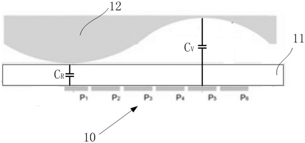
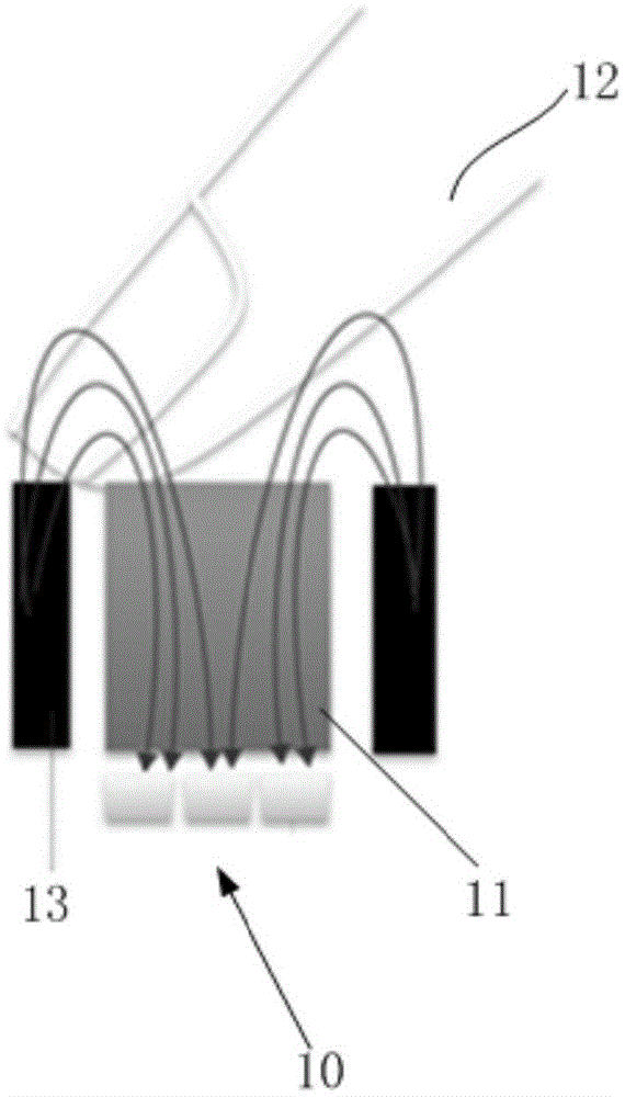
[0028] Such as Figure 4 As shown, this embodiment relates to a glass coating structure, which is mainly used in a capacitive press fingerprint detection system and serves as an isolation layer covering a capacitive fingerprint sensor. The structure of the glass coating includes a glass base 1 and the Alternately stacked titanium oxynitride coating layers 2 and silicon oxynitride coating layers 3 are arranged downward on the lower surface of the glass substrate, and the overall coating layer structure formed by the multilayer coating layers is also called a film system.

[0029] Among them, in the molecular formulas of titanium oxynitride and silicon oxynitride, the ratio of nitrogen to oxygen is roughly between 0.8:1 and 1:1. In practical applications, it is more preferable to set the ratio of nitrogen to oxygen at 0.9 :1, that is, the molecular formula of titanium oxynitride and silicon oxynitride can be expressed as TIN x o y and SIN x o y , where x=0.9y.

[0030] In t...

Embodiment 2

[0037] On the basis of Embodiment 1, this embodiment provides a specific coating structure: the total number of the coating layers is 6 layers, and the total thickness of the coating layer of the titanium oxynitride is different from that of the silicon oxynitride. The ratio of the total thickness of the coating layer is between 0.4 and 0.5, ensuring this ratio can achieve a silver mirror effect with only 6 coating layers, and can control the total thickness below 550nm, thereby reducing the capacitance detection impact.

[0038] Among them, the structure of each layer can adopt the following thickness distribution:

[0039] The first coating layer is a titanium nitride oxide coating with a thickness in the range of 50-80nm;

[0040] The second coating layer is a silicon nitride oxide coating with a thickness in the range of 70-120nm;

[0041] The third coating layer is a titanium nitride oxide coating with a thickness in the range of 20-40nm;

[0042] The fourth coating la...

Embodiment 3

[0051] Such as Figure 5 As shown, in this embodiment, on the basis of the above-mentioned embodiments, a layer of black ink is provided under the entire plating layer. By providing the ink layer, light can be better shielded and interference from stray light can be prevented.

[0052] Further, it is also possible to print a certain hollow pattern when printing the black ink layer, for example, to print a hollow pattern of fingerprint graphics, the hollowed part and the non-hollowed part have differences in light transmittance and reflectivity, so that from The observation on the upper layer of glass will present a corresponding pattern on the mirror background, so that the fingerprint area can be marked or decorated. Preferably, a pigment different from black can be placed in the hollow pattern, more preferably, a pigment that contrasts with gray can be filled, for example, white pigment can be filled, so as to make the pattern more obvious.


PUM

PropertyMeasurementUnit
thicknessaaaaaaaaaa
thicknessaaaaaaaaaa
thicknessaaaaaaaaaa

Abstract

The invention provides a glass coating structure manufacturing method. The method comprises feeding nitrogen and oxygen into a vacuum space of which the upper part is provided with a glass substrate according to a fixed ratio of nitrogen to oxygen of 0.8: 1 to 1: 1 and alternately carrying out a titanium-nitrogen oxide coating film formation process and a silicon-nitrogen oxide coating film formation process to downward form alternately overlapped silicon-nitrogen oxide coating films and titanium-nitrogen oxide coating films at the lower surface of the glass substrate. The silicon-nitrogen oxide coating film and titanium-nitrogen oxide coating film are alternately overlapped at the lower surface of the glass substrate and nitrogen-oxygen ratios are the same and are in a range of 0.8: 1 to 1: 1 so that insulating properties are guaranteed, a glass coating structure with minute surface effects is formed and coating thickness has small influence on fingerprint detection in a very small range.

Description

technical field [0001] The invention relates to a method for manufacturing a glass coating structure, in particular to a method for manufacturing a glass coating structure applied to fingerprint detection. Background technique [0002] At present, the fingerprint identification technology has been applied to products such as mobile terminals (eg, computers). Among them, the capacitive pressing fingerprint detection method is widely used, and is specifically divided into active pressing detection and passive pressing detection. [0003] The basic principle of passive press detection is as follows figure 1 As shown, the entire detection system includes: a capacitive fingerprint sensor 10 at the bottom and an isolation layer (or called a protective layer, which is also an area directly touched by fingers) 11 covering the capacitive fingerprint sensor 10, wherein the capacitive fingerprint sensor 10 includes a plurality of capacitive plates arranged in a two-dimensional array ...

Claims


Application Information

Patent Timeline
Patent Type & Authority Applications(China)
IPC IPC(8): C03C17/34
CPCC03C17/3435C03C2217/70C03C2218/152C23C14/18C23C14/24
Inventor 苏斌
Owner LEMOBILE INFORMATION TECH BEIJING
Why Eureka
Try Eureka