Permanent magnet bias single-degree-of-freedom axial magnetic bearing

An axial magnetic bearing and permanent magnet bias technology, applied in the field of bearing manufacturing, can solve the problems of low rotor strength, low rotational speed, large magnetic leakage, low critical rotational speed, etc., and achieve large axial suspension force, low power consumption, and reduced leakage. magnetic effect

Active Publication Date: 2016-08-10
金湖县项目服务中心
View PDF8 Cites 6 Cited by
  • Summary
  • Abstract
  • Description
  • Claims
  • Application Information

AI Technical Summary

Problems solved by technology

[0004] At present, according to the different structural forms of the permanent magnet bias axial magnetic bearing, it can be divided into three types, , Placing the permanent magnet in the rotor makes its installation more difficult, and the low strength of the rotor limits the increase of its speed; , The magnetic bearing places the suspended rotor on both sides of the stator, the axial length is long, and the critical speed is low; 2. The axial control magnetic flux in the magnetic bearing passes through the permanent magnet, which has an obvious demagnetization effect on the permanent magnet. The magnetic flux leakage is large, and the reluctance of the permanent magnet is large, resulting in a large current required to generate the same axial levitation force. High power consumption, its field of application is limited

Method used


Image

  • Permanent magnet bias single-degree-of-freedom axial magnetic bearing
  • Permanent magnet bias single-degree-of-freedom axial magnetic bearing

Examples


Embodiment Construction

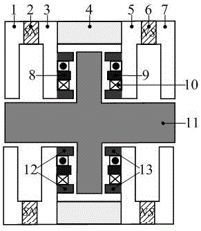
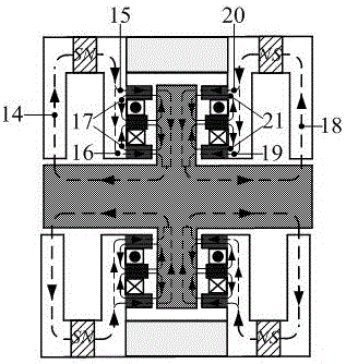
[0026] The present invention is based on the principle that the axially magnetized left annular permanent magnet 2 generates a left static bias magnetic flux 14, and the left static bias magnetic flux 14 starts from the N pole of the left annular permanent magnet 2 and passes through the magnetic field. The stator core 3 on the left side of the bearing is divided into two parts, namely the magnetic flux 15 and the magnetic flux 16, which enter the axial working air gap from the suction disc 12, the radial part of the rotor core 11, and the axial part of the rotor core 11 , left iron core bridge iron core air gap, left iron core bridge iron core 1 returns to the S pole of left annular permanent magnet 2, forms a closed magnetic circuit. The axially magnetized right annular permanent magnet 6 generates the right static bias magnetic flux 18, and the right static bias magnetic flux 18 starts from the N pole of the right annular permanent magnet 6 and passes through the right stato...


PUM


Abstract

The invention discloses a permanent magnet bias single-degree-of-freedom axial magnetic bearing. The permanent magnet bias single-degree-of-freedom axial magnetic bearing comprises a stator and a rotor iron core. The rotor iron core comprises an axial part and a radial part. The stator comprises a left side iron core bridge iron core, a right side iron core bridge iron core, a left side annular permanent magnet, a right side annular permanent magnet, a magnetic bearing left side stator iron core and a magnetic bearing right side stator iron core, wherein the left side iron core bridge iron core and the right side iron core bridge iron core are symmetrically arranged with the radial part of the rotor iron core as the symmetric center and arranged along the axial part of the rotor iron core, the left side annular permanent magnet and the right side annular permanent magnet are symmetrically arranged with the radial part of the rotor iron core as the symmetric center and arranged along the axial part of the rotor iron core, the magnetic bearing left side stator iron core and magnetic bearing right side stator iron core are symmetrically arranged with the radial part of the rotor iron core as the symmetric center and arranged along the axial part of the rotor iron core, and the left side iron core bridge iron core and the right side iron core bridge iron core, the left side annular permanent magnet and the right side annular permanent magnet and the magnetic bearing left side stator iron core and magnetic bearing right side stator iron core are sequentially arranged. A magnetism isolation aluminum ring is arranged between the magnetic bearing left side stator iron core and magnetic bearing right side stator iron core. The magnetic bearing left side stator iron core and magnetic bearing right side stator iron core are each of an E-shaped structure. A control winding is manufactured in each stator groove in a winding manner. The permanent magnet bias single-degree-of-freedom axial magnetic bearing effectively overcomes the defects of an existing axial magnetic bearing, and the low-power-consumption single-degree-of-freedom axial magnetic bearing easy to control, manufacture and assemble and capable of controlling magnetic flux not to pass through the permanent magnets and the rotor axial iron cores and generating larger axial levitation force is provided.

Description

technical field [0001] The invention relates to the technical field of bearing manufacturing, in particular to a low-power permanent magnet bias unit with simple control, manufacture and assembly, and the control magnetic flux does not pass through the permanent magnet and the axial iron core of the rotor, which can generate greater axial levitation force degrees of freedom axial magnetic bearings. Background technique [0002] The magnetic bearing is a new type of high-performance bearing that uses the electromagnetic force between the stator and the rotor to suspend the rotor in space, so that there is no mechanical contact between the stator and the rotor. Since there is no mechanical contact between the stator and the rotor, the suspension rotor supported by the magnetic suspension bearing can reach a high operating speed, and has the advantages of no mechanical wear, low energy consumption, long life, no lubrication, no pollution, etc., especially suitable for applicati...

Claims


Application Information

Patent Timeline
Patent Type & Authority Applications(China)
IPC IPC(8): F16C32/04
CPCF16C32/0406F16C32/0474
Inventor 张涛莫丽红张晨倪伟丁卫红叶小婷张惠萍
Owner 金湖县项目服务中心
Why Eureka
Try Eureka