Unlock instant, AI-driven research and patent intelligence for your innovation.

Temperature control device and temperature control method based on FPGA for optical amplifier

A technology of a temperature control device and a temperature control method, which is applied in the field of optical communication, can solve the problems of long loop control time, cost increase, impact on cost and effect, etc., and achieve the effects of strict timing, long cycle, and long calculation cycle

Active Publication Date: 2016-08-10
GUANGXUN SCI & TECH WUHAN
View PDF7 Cites 18 Cited by
  • Summary
  • Abstract
  • Description
  • Claims
  • Application Information

AI Technical Summary

Problems solved by technology

[0004] Temperature control can be studied from two aspects of hardware and software. Different hardware and software control circuits affect cost and effect
For example, the patent "A TEC temperature controller based on single-chip microcomputer for optical fiber system" (Patent No. 201410465948.4) uses a single-chip microcomputer for temperature control, and the software operation is easily affected by external interruptions, and the loop control time is long and uncertain, realizing multi-channel When controlling functions, the control time has a linear growth relationship with the number of channels
The patent "Laser Temperature Control Circuit Based on TEC" (Patent No. 201410479411.3) uses the dedicated integrated chip MAX1978 to complete temperature control. The drive current of MAX1978 is limited. The device has consistency problems and is easily affected by noise. To realize multi-channel control, the MAX1978 chip needs to be doubled, and the cost is significantly increased.

Method used


Image

  • Temperature control device and temperature control method based on FPGA for optical amplifier
  • Temperature control device and temperature control method based on FPGA for optical amplifier
  • Temperature control device and temperature control method based on FPGA for optical amplifier

Examples


Embodiment Construction

[0026] The FPGA-based temperature control device and method for optical amplifiers of the present invention will be further described below in conjunction with the accompanying drawings.

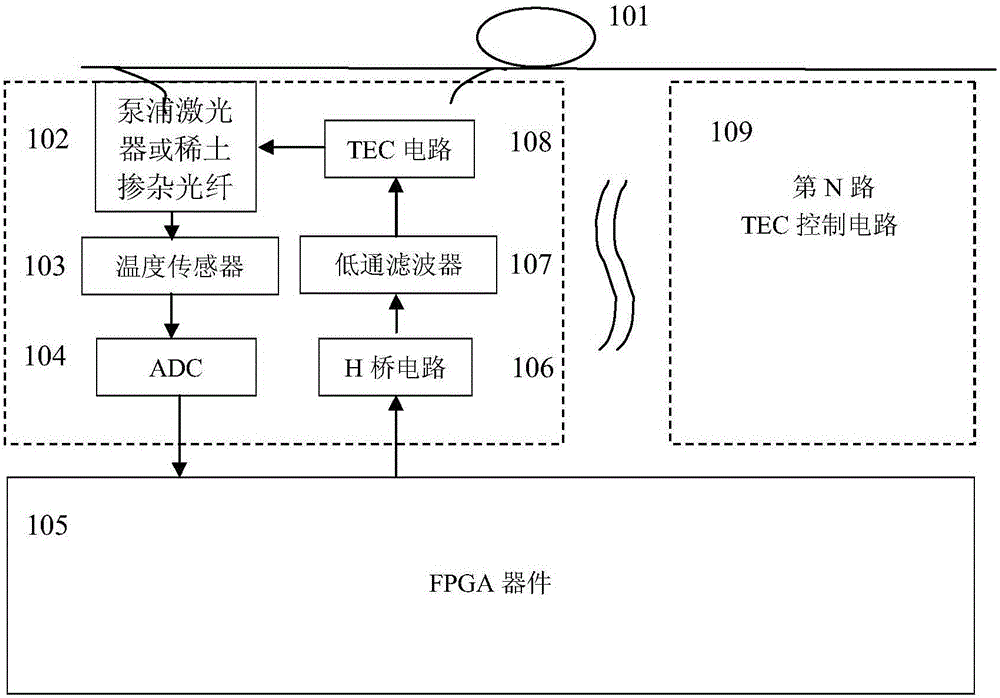
[0027] Embodiments of the present invention are as figure 1 As shown, an FPGA-based temperature control device for an optical amplifier includes: a heating target such as a pump laser or a rare-earth doped optical fiber 102, a temperature sensor 103, a high-precision ADC analog-to-digital conversion chip 104, an FPGA device 105, and an H bridge Circuit 106, low-pass filter 107, TEC circuit 108; the heating target is placed in a metal box and connected to the temperature sensor; the temperature sensor outputs an analog signal and is connected to the ADC analog-to-digital conversion chip; the ADC outputs a digital signal to FPGA; FPGA calculates As a result, the control signal is output to the H-bridge; the H-bridge is connected with a low-pass filter, and the low-pass filter outputs the signa...


PUM


Abstract

The invention provides a temperature control device and a temperature control method based on a programmable logic device (FPGA) for an optical amplifier. The temperature control device comprises the components of ADC analog-to-digital conversion chip, an FPGA device, an H-bridge circuit, a low-pass filter, a TEC circuit, a temperature sensor and a communication interface. According to the temperature control method and the temperature control device, a requirement for constant temperature of the optical amplifier is realized by means of the FPGA device, the TEC control circuit, etc. The ADC analog-to-digital conversion chip samples a temperature sensor signal and obtains an actual temperature. The FPGA device realizes a control algorithm and outputs a corresponding pulse width modulation signal (PWM wave) according to the difference between an objective temperature and an actual temperature. The H-bridge circuit improves load bearing capability of the FPGA device and outputs a large current. The low-pass filter prevents cliffy edge of the PWM wave and filters harmful high-frequency noises of the PWM wave. When the objective temperature is higher than the actual temperature, the current flows in from the positive end of a TEC, and the TEC is in a heating state for increasing the temperature, and otherwise, the TEC reduces the temperature. Furthermore, through adjusting the duty ratio of the PWM wave, the magnitude of the H-bridge current is controlled, thereby satisfying requirements for high temperature precision and time adjustment.

Description

technical field [0001] The invention belongs to the technical field of optical communication, in particular to an FPGA-based temperature control device and method for an optical amplifier. Background technique [0002] TEC is a device that uses the thermo-electric effect of semiconductors to produce cold energy. When a semiconductor is connected to dissimilar metals and a direct current is applied, the temperature at one junction decreases and the temperature at the other junction increases. If the current direction is opposite, the temperature change is opposite. Integrate TEC into the chip or module to control the temperature change [0003] The optical amplifier is one of the key modules in the optical communication network. The pump laser and the rare earth doped fiber are the core components of the optical amplifier, which directly determine the optical characteristics of the optical amplifier. The pump laser will generate a lot of heat during operation, the temperat...

Claims


Application Information

Patent Timeline
IPC IPC(8): G05D23/20
CPCG05D23/20
Inventor 于龙余春平
Owner GUANGXUN SCI & TECH WUHAN