
An emission reduction system for fine particulate matter in iron ore sintering process

A fine particle and sintering process technology, applied in the direction of dispersed particle separation, gas treatment, membrane technology, etc., can solve the problems of large flue gas flow rate, complex composition, and limited emission reduction effect

Active Publication Date: 2018-02-02
ANHUI UNIVERSITY OF TECHNOLOGY
View PDF13 Cites 0 Cited by
  • Summary
  • Abstract
  • Description
  • Claims
  • Application Information

AI Technical Summary

Problems solved by technology

[0009] (5) The composition of flue gas is complex, which contains a variety of pollutants, such as: fine particulate matter, SO 2 , COx, NOx, HCl, HF and dioxins, etc.
Such as: the name of the invention: industrial kiln flue gas PM 2.5 Dust and heavy metal treatment and removal device [9] , (Chinese patent number: ZL201220721358.X, application date: 2012-12-24), by setting a filter bag on the flue gas passage and placing the bag cage inside the filter bag, the PM 2.5 Dust emission reduction; this technology has a good emission reduction effect on large particle pollutants, but the PM in the flue gas 2.5 The emission reduction effect is limited
In addition, the name of the invention is: a method for segmental circulation of iron ore sintering flue gas [10] (Chinese patent number: ZL201310443223.0, application date: 2013-09-26), a method for energy saving and emission reduction of iron ore sintering [11] (Chinese patent number: ZL201510137762.0, application date: 2015-03-27), etc., these technical solutions can realize the coordinated emission reduction of various pollutants in the sintering flue gas, although it can reduce the emission of large particles of dust in the flue gas ; but the emission reduction effect on fine particulate matter in sintering flue gas is extremely limited
In addition, compared with other exhaust gases, sintering flue gas has complex composition and huge flue gas flow rate, so that effective emission reduction technologies suitable for fine particulate matter in sintering flue gas have not yet been developed.

Method used


Image

  • An emission reduction system for fine particulate matter in iron ore sintering process
  • An emission reduction system for fine particulate matter in iron ore sintering process
  • An emission reduction system for fine particulate matter in iron ore sintering process

Examples


Embodiment 1

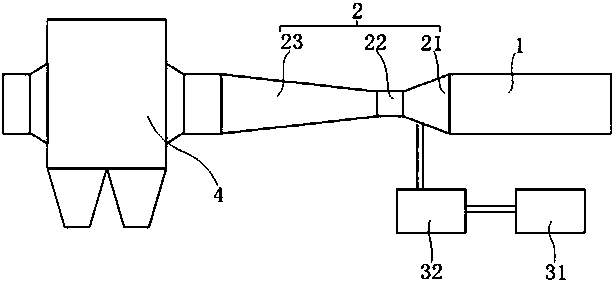
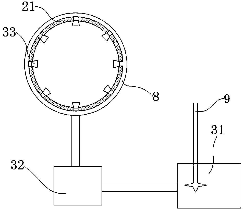
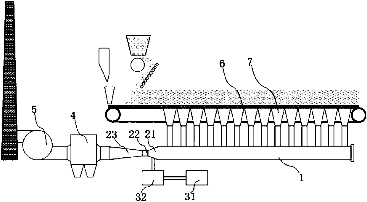
[0058] combine figure 1 , 2 , 3 and 4, a kind of iron ore sintering process fine particle emission reduction system of the present embodiment includes a fine particle atomization and agglomeration device 2, agglomeration liquid adding device and dust removal device 4, and the sintering mixture is mixed and granulated Finally, the material distributing device is installed on the sintering and sintering trolley 6. The sintering mixture is ignited and then ventilated and sintered. The sintering flue gas passes through the sintering material layer. The flue gas flows into the main flue 1 from the bottom of the sintering trolley 6 through the bellows 7. The main flue 1 is equipped with an atomization agglomeration device 2, an agglomeration liquid adding device and a dust removal device 4. The flue gas flows into the atomization from the main flue 1. The agglomeration device 2 is discharged into the chimney by the fan 5 after being dedusted by the dust removal device 4; the fine p...

Embodiment 2

[0105] The basic content of this embodiment is the same as that of Example 1, except that the additive is composed of activated carbon and zeolite, and the additive is composed of the following mass percentages: 85% activated carbon, 15% zeolite, and the particle size requirements of the activated carbon: 74μm≤activated carbon particle size≤100μm, zeolite particle size requirement: 74μm≤zeolite particle size≤100μm.

[0106] Detect the emission concentration of PM2.5 and PM10 in the sintering flue gas after dust removal device 4, and calculate the emission reduction efficiency of PM2.5 and PM10. The emission reduction efficiency of PM2.5 is 56.4%, and the emission reduction efficiency of PM10 is 49.0%.

Embodiment 3

[0108] The basic content of this embodiment is the same as that of Example 1, except that the additive is composed of activated carbon and zeolite, and the additive is composed of the following mass percentages: 95% activated carbon and 5% zeolite.

[0109] Detect the emission concentration of PM2.5 and PM10 in the sintering flue gas after dust removal device 4, and calculate the emission reduction efficiency of PM2.5 and PM10. The emission reduction efficiency of PM2.5 is 60.2%, and the emission reduction efficiency of PM10 is 48.8%.


PUM

PropertyMeasurementUnit
particle diameteraaaaaaaaaa

Abstract

The invention discloses an emission reduction system for fine particles in the sintering process of iron ore, and belongs to the technical field of emission reduction of pollutants in the sintering process of iron ore. The emission reduction system for fine particles in the sintering process of iron ore comprises a fine particle atomizing and agglomerating device, an agglomerating liquid adding device and a dust removing device. The bottom of a sintering pallet is connected with a main flue through air bellows, air draft smoke is combined in the main flue through the bottom of the sintering pallet via the air bellows, the atomizing and agglomerating device, the agglomerating liquid adding device and the dust removing device are arranged on the main flue, and the smoke flows into the atomizing and agglomerating device from the main flue, and is subjected to dust removal by the dust removing device and then discharged into a chimney by a draught fan. By means of the emission reduction system, agglomerating liquid fog drops with fine particles adsorbed nucleate, collide and grow under the low-pressure condition, and form large particle agglomerated mater, the fine particles growing through agglomeration are removed with the dust removing device, and thus a bran-new emission reduction approach is provided for emission reduction of the fine particles in the sintering process of iron ore.

Description

technical field [0001] The invention relates to the technical field of pollutant emission reduction in the iron ore sintering process, and more specifically, relates to an emission reduction system for fine particles in the iron ore sintering process. Background technique [0002] Inhalable particulate matter refers to the general term for particulate matter that can enter the human respiratory tract through the nose and mouth, represented by PM10 (particles with an aerodynamic diameter of less than 10 microns in the ambient air). PM2.5 refers to particulate matter in the ambient air with an aerodynamic equivalent diameter less than or equal to 2.5 microns. It can be suspended in the air for a long time, and the higher its concentration in the air, the more serious the air pollution. Although PM2.5 is only a small component of the earth's atmospheric composition, it has an important impact on air quality and visibility. Compared with coarser atmospheric particles, PM2.5 ha...

Claims


Application Information

Patent Timeline
Patent Type & Authority Patents(China)
IPC IPC(8): B01D51/04
CPCB01D51/04B01D2258/025
Inventor 春铁军吴雪健龙红明李家新狄瞻霞王平孟庆民宁超钱立新王欢
Owner ANHUI UNIVERSITY OF TECHNOLOGY
Learn More