Coating mechanism, slit coating device and film preparation method
A coating and film forming technology, which is applied to the surface coating liquid device, coating, and final product manufacturing, can solve the problems of high cost and poor film forming quality, and achieve low cost and easy mass production , enhance the effect of infiltration
- Summary
- Abstract
- Description
- Claims
- Application Information
AI Technical Summary
Problems solved by technology
Method used
Image

Examples
Embodiment 1
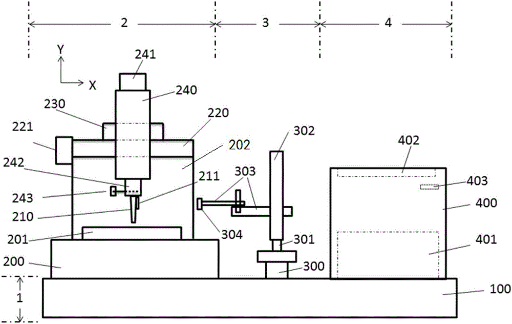
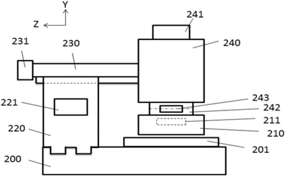
[0036] In this embodiment, a coating mechanism 2 is provided, please refer to figure 1 , figure 1 This is a structural diagram of the slit coating device in the embodiment of this application, such as figure 1 As shown, the coating mechanism 2 includes: a base 200, a pallet 201, a movable support member 202, and a fluid storage tank 240 with a nozzle 210; the pallet 201 and the movable support member 202 are both fixed in the The base 200; wherein, the fluid storage tank 240 is fixed on the movable support member 202 to move relative to the pallet 201 under the drive of the movable support member 202; wherein, in the During the movement of the fluid storage tank 240, the fluid material in the fluid storage tank 240 is applied to the sample to be coated fixed on the pallet 201 through the nozzle 210 to form a film directly.
[0037] Specifically, the sample may be one or more of a positive pole piece or a negative pole piece.
[0038] In the specific implementation process, the slit...
Embodiment 2
[0057] In this embodiment, a slit coating device is provided, such as figure 1 As shown, the device includes:
[0058] Horizontal support platform 1; the horizontal support platform 1 is fixed with the coating mechanism 2, the base material transfer mechanism 3, and the film forming thermostat 4 provided in the first embodiment;
[0059] Wherein, the base material transfer mechanism 3 is located between the coating mechanism 2 and the film-forming incubator 4 to transfer the coated sample to the film-forming incubator 4 for heating to form a film.
[0060] Since the coating mechanism 2 has been introduced in detail in the first embodiment, it will not be repeated here.
[0061] First, the base material transfer mechanism 3 is introduced.
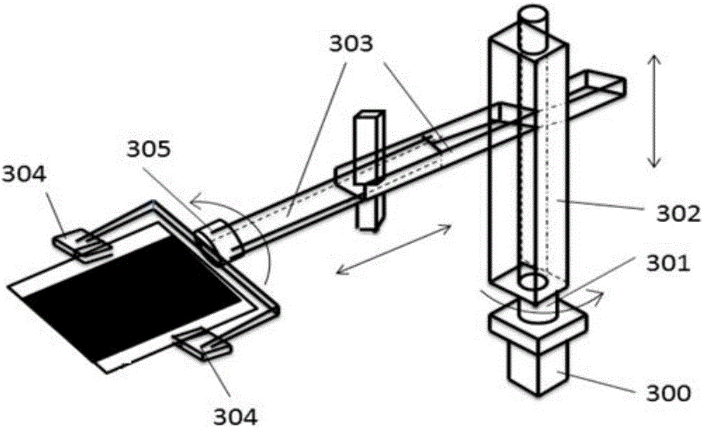
[0062] The main function of the base material transfer mechanism 3 is to realize the clamping, transfer and upside down of samples.
[0063] In the embodiments of this application, such as figure 1 with image 3 As shown, the base material transfer mec...
Embodiment 3
[0081] In this embodiment, a film preparation method is provided, please refer to Figure 5 , Figure 5 This is a step diagram of a film preparation method in an embodiment of this application. The method is applied to the slit coating device described in Embodiment 2. The method includes:
[0082] In step S501, the fluid storage tank 240 is moved relative to the pallet 201 under the drive of the movable support member 202, and the fluid material is uniformly applied to the pallet 201 through the nozzle 210 and fixed On the sample to be coated;
[0083] Step S502, the base material transfer mechanism 3 transfers the coated sample to the film forming thermostat 4;
[0084] In step S503, the coated sample is heated by the film forming thermostat 4 to form a film on the surface of the sample.
[0085] The following is an example of film formation on both sides of the sample to illustrate the method:
[0086] First, the fluid storage tank 240 is moved under the drive of the movable support...
PUM
 Abstract
Description
Claims
Application Information
 - R&D
- Intellectual Property
- Life Sciences
- Materials
- Tech Scout
- Unparalleled Data Quality
- Higher Quality Content
- 60% Fewer Hallucinations
Browse by: Latest US Patents, China's latest patents, Technical Efficacy Thesaurus, Application Domain, Technology Topic, Popular Technical Reports.
© 2025 PatSnap. All rights reserved.Legal|Privacy policy|Modern Slavery Act Transparency Statement|Sitemap|About US| Contact US: help@patsnap.com