
Powerful high-speed electromagnetic valve

A solenoid valve and electromagnet technology, applied in the field of solenoid valves, can solve the problems that solenoid valves are difficult to meet technical requirements, and achieve the effects of improving fuel economy, low inductance, and large electromagnetic force

Inactive Publication Date: 2016-08-24
桑宇宏
View PDF13 Cites 3 Cited by
  • Summary
  • Abstract
  • Description
  • Claims
  • Application Information

AI Technical Summary

Problems solved by technology

With the implementation of increasingly stringent national environmental protection regulations, the requirements for reducing and reducing harmful substances in vehicle exhaust emissions are getting higher and higher, and the solenoid valves of existing known technologies have been difficult to meet the relevant technical requirements.

Method used


Image

  • Powerful high-speed electromagnetic valve
  • Powerful high-speed electromagnetic valve
  • Powerful high-speed electromagnetic valve

Examples


Embodiment Construction

[0023] The following is attached Figure 1 to Figure 5 To describe and illustrate the present invention in detail:

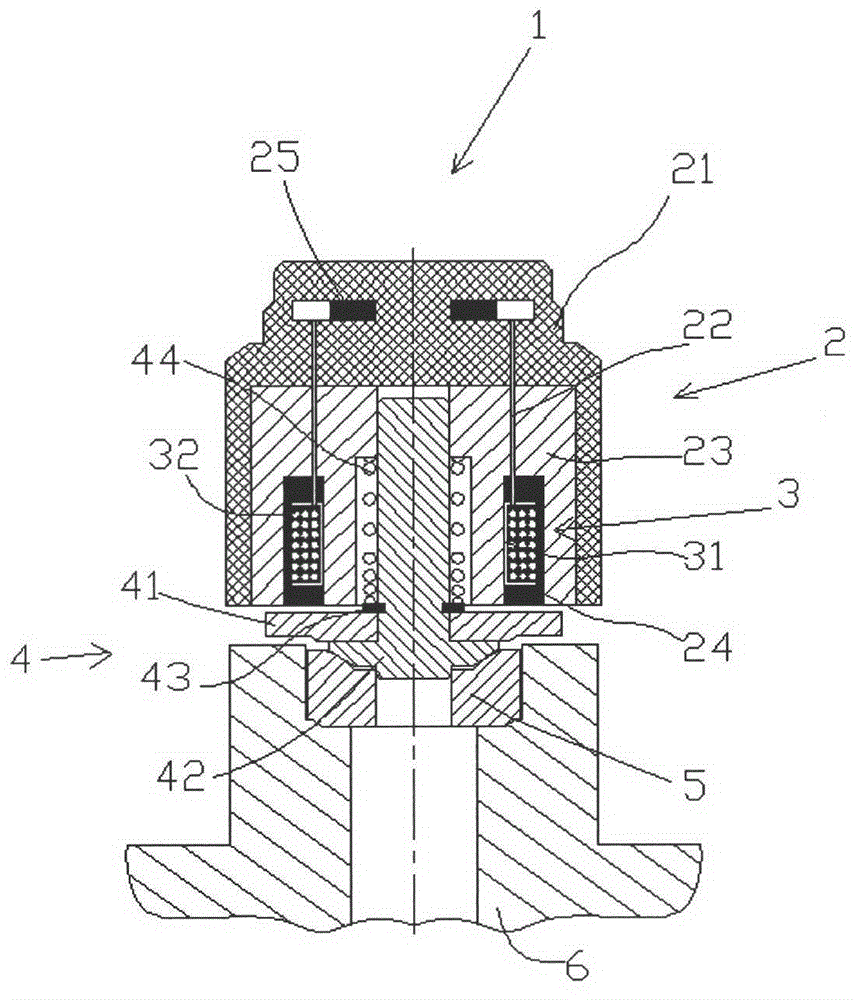
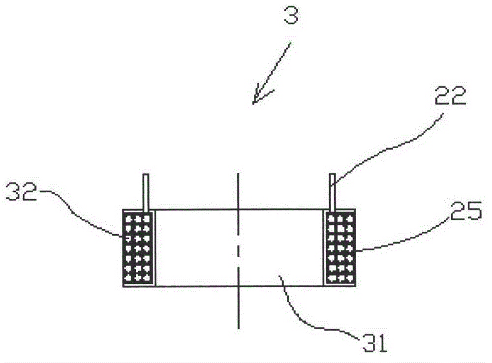
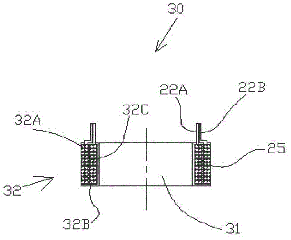
[0024] figure 1 It is a schematic structural diagram of a solenoid valve 1 in the prior art. The solenoid valve 1 is mainly composed of an electromagnet assembly 2 , an armature valve stem movement assembly 4 , a valve seat 5 , and a valve seat base 6 . The electromagnet assembly 2 is composed of an electromagnet casing 21, an iron core 23, an electromagnetic coil skeleton assembly 3, a copper terminal 22, an electrode 25, an electromagnetic coil sealing glue 24, and the like. The shell 21 of the electromagnet is made of non-magnetic metal aluminum-copper alloy or polymer material, and the iron core 23 is made of silicon steel laminations and soft magnetic materials (electrical pure iron, iron-silicon alloy, iron-phosphorus alloy, iron-cobalt alloy ) is processed; the electromagnetic coil skeleton assembly 3 is assembled and placed in the inner ring groove at ...


PUM


Abstract

The invention discloses a powerful high-speed electromagnetic valve. The powerful high-speed electromagnetic valve is characterized in that an electromagnetic coil in an electromagnet comprises two or more mutually independent windings; the coil windings are wound on a polymer skeleton in certain sequence; after being connected in parallel, terminals of the windings are connected with a control electrode through copper binding posts; wire diameters and number of turns of the windings in the coil can be the same and can be different; transverse sections of the windings can be circular, oval, square, rectangular, triangular, polygonal, and the like; longitudinal sections of the windings are rectangular, trapezoidal, outside-convex inside-concave circular arc-shaped and crescent-shaped; and relative positions of the windings in the coil can be arbitrarily arranged and are not limited. The high-speed electromagnetic valve has the characteristics that the impedance is low, the inductance is low, the electromagnetic force is high, the structure is compact, the dynamic response speed of an armature valve rod motion component is high, and the like, and the high quality requirement of different working conditions and different load conditions of an internal combustion engine on fuel injection principle and injection form can be met.

Description

[0001] technology [0002] The invention relates to a solenoid valve for fuel injection control and regulation. Background technique [0003] Solenoid valves are widely used in fuel electronically controlled injection systems of internal combustion engines to precisely control fuel injection quantity and injection timing. The electromagnetic force and dynamic response performance of solenoid valves directly affect the engine's power, fuel economy, and exhaust emissions. harmful emissions. When the engine is working, the duration of fuel injection is very short, and the solenoid valve is required to generate a strong electromagnetic force to drive the armature valve stem moving component to move quickly in a very short period of time. The technical performance of the solenoid valve mainly depends on the magnitude of the electromagnetic force and the dynamic response performance of the armature valve stem movement component after power is applied. With the implementation of in...

Claims


Application Information

Patent Timeline
IPC IPC(8): F16K31/06F02M61/04
Inventor 桑宇宏
Owner 桑宇宏
Learn More