
A Method for Observing the Expansion Process of Soil Shear Band under Confining Pressure

A technology of extended process and shear band, applied in the field of geotechnical engineering, can solve problems such as poor operability, poor use effect, and complex device structure

Active Publication Date: 2018-07-03
XIAN UNIV OF SCI & TECH
View PDF13 Cites 0 Cited by
  • Summary
  • Abstract
  • Description
  • Claims
  • Application Information

AI Technical Summary

Problems solved by technology

Existing observation methods for the expansion process of soil shear bands have problems such as complex device structure, high test cost, cumbersome test process, poor operability, and poor use effect to varying degrees. The most important thing is that they cannot be simple, fast and accurate. Analyzing the soil microstructure of the shear zone, it is impossible to understand the influence of the soil microstructure on the macroscopic performance of the soil shear zone, and it is impossible to establish the relationship between the soil microstructure characteristics of the soil shear zone and its macroscopic performance. contact
In addition, it should be noted that most of the existing shear test devices cannot provide confining pressure during the shear test, and cannot better simulate the stress state of the soil

Method used


Image

  • A Method for Observing the Expansion Process of Soil Shear Band under Confining Pressure
  • A Method for Observing the Expansion Process of Soil Shear Band under Confining Pressure
  • A Method for Observing the Expansion Process of Soil Shear Band under Confining Pressure

Examples


Embodiment 2

[0215] In this example, the difference from Example 1 is that the curing solution described in step 203 is uniformly composed of epoxy resin, acetone, ethylenediamine and dibutyl phthalate in a volume ratio of 100:170:6:2.2 mixed.

[0216] In this embodiment, the remaining method steps are the same as those in Embodiment 1.

Embodiment 3

[0218] In this example, the difference from Example 1 is that the curing solution described in step 203 is uniformly composed of epoxy resin, acetone, ethylenediamine and dibutyl phthalate in a volume ratio of 100:170:8:1.8 mixed.

[0219] In this embodiment, the remaining method steps are the same as those in Embodiment 1.

Embodiment 4

[0221] In this example, the difference from Example 1 is that the curing solution described in step 203 is uniformly composed of epoxy resin, acetone, ethylenediamine and dibutyl phthalate in a volume ratio of 100:130:8:1.8 mixed.

[0222] In this embodiment, the remaining method steps are the same as those in Embodiment 1.


PUM

PropertyMeasurementUnit
heightaaaaaaaaaa
heightaaaaaaaaaa

Abstract

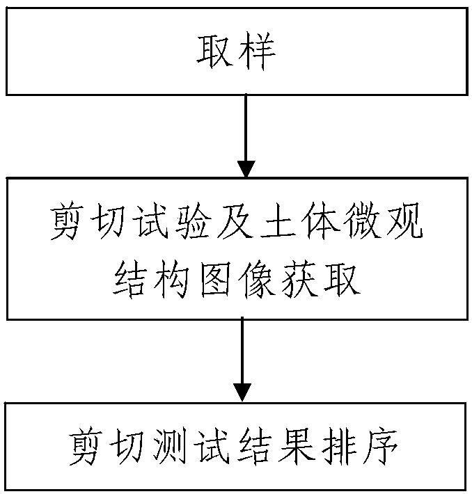
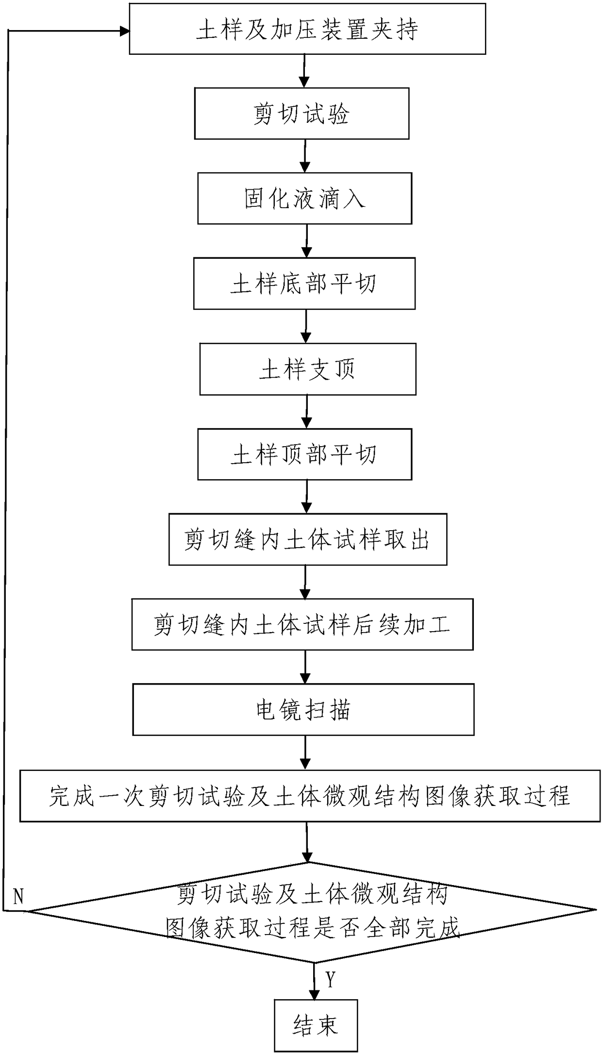
The invention discloses a method for observing expansion procedures of soil mass shear bands in confining pressure states. The method includes steps of firstly, sampling soil; secondly, carrying out shear tests, acquiring images of microscopic structures of soil masses, acquiring shear test results of to-be-tested soil samples at a plurality of different depth positions on the to-be-tested soil mass shear bands in the confining pressure states; thirdly, ranking the shear test results. When the shear tests are carried out on the to-be-tested soil samples and the images of the microscopic structures of the soil masses are acquired, procedures include clamping the soil samples and pressure devices, carrying out the shear tests, dropping solidifying liquid into the soil samples, flatly cutting the bottoms of the soil samples, propping the soil samples, flatly cutting the tops of the soil samples, fetching soil mass test specimens out of shear gaps, carrying out subsequent treatment on soil mass test specimens in the shear gaps and scanning the soil mass test specimens by the aid of electron microscopes. The method has the advantages that the method includes the simple steps, is reasonable in design and easy and convenient to implement, good service effects can be realized, the shear strength of the different depth positions on the tested soil mass shear bands in the confining pressure states and microscopic structures of shear positions can be easily, conveniently and quickly acquired, and accordingly the expansion procedures of the soil mass shear bands in the confining pressure states can be easily, conveniently and visually observed.

Description

technical field [0001] The invention belongs to the technical field of geotechnical engineering, and in particular relates to a method for observing the expansion process of a soil shear zone under a confining pressure state. Background technique [0002] In recent years, the transformation of the natural environment by human activities has become more and more intense. Human engineering activities have caused many geological disasters and caused huge damage to people's lives and properties. Among them, the slope instability induced by human activities is the most serious, and the focus of research on slope instability is to study the deformation and expansion process of the soil shear zone. The shear zone refers to the strong deformation zone developed in the lithosphere or soil and has shear strain. The shear zone developed in the soil is the soil shear zone. This deformation zone can be a planar structure (fault) with discontinuous strain, or a ductile shear zone with c...

Claims


Application Information

Patent Timeline
Patent Type & Authority Patents(China)
IPC IPC(8): G01N3/24G01N3/02G01N3/06
CPCG01N3/02G01N3/068G01N3/24G01N2203/0025G01N2203/0647
Inventor 王晓华李晓军李昊李洁梁
Owner XIAN UNIV OF SCI & TECH
Learn More