High-low-temperature in situ XRD analyzing and testing method for lithium iron phosphate electrode material

A lithium iron phosphate and electrode material technology, applied in the field of nanomaterials and electrochemical in-situ analysis, can solve problems such as bad hidden dangers, and achieve the effect of optimizing low-temperature performance and improving low-temperature degradation performance

Inactive Publication Date: 2016-08-24
WUHAN UNIV OF TECH
View PDF0 Cites 4 Cited by
  • Summary
  • Abstract
  • Description
  • Claims
  • Application Information

AI Technical Summary

Problems solved by technology

The service life of lithium iron phosphate battery is closely related to its use temperature. If the use temperature i

Method used


Image

  • High-low-temperature in situ XRD analyzing and testing method for lithium iron phosphate electrode material
  • High-low-temperature in situ XRD analyzing and testing method for lithium iron phosphate electrode material
  • High-low-temperature in situ XRD analyzing and testing method for lithium iron phosphate electrode material

Examples


Embodiment 1

[0020] 1) Lithium carbonate, ferrous oxalate, ammonium dihydrogen phosphate, add an appropriate amount of acetylene black according to the stoichiometric ratio, and mill in a high-energy ball mill for 1 hour. The above materials are kept at 600°C for 4 hours in an argon atmosphere to obtain lithium iron phosphate;

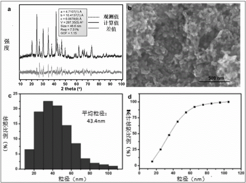
[0021] 2) Through step 1) you can get figure 1 (a) XRD pattern and figure 1 (b) SEM topography; the obtained lithium iron phosphate electrode material, acetylene black, and PTFE are ground in a mass ratio of 6:3:1; the electrode material is obtained, and the in-situ battery is assembled, and the cycle performance (such as figure 2 ) and good rate performance;

[0022] 3) The in-situ battery is tested with a high and low temperature test mold, and the change of the XRD peak of the material during the reaction process is observed at the same time. The specific steps are: use the X-ray light source of the general laboratory, set the in-situ test program to obtain a...

Embodiment 2

[0027] Constant current high temperature room temperature test

[0028] 1) Stir lithium nitrate, ferrous oxalate and citric acid in deionized water, add ammonium dihydrogen phosphate, add an appropriate amount of PEG (polyethylene glycol), stir for 6 hours to obtain a uniform solution, and dry at 80°C for 24 hours to obtain a powder. Grind the powder, and sinter the uniformly ground powder at 600°C under an argon atmosphere to obtain a lithium iron phosphate electrode material sample. figure 1 To obtain the XRD pattern of the sample;

[0029] 2) Mix the obtained lithium iron phosphate electrode material sample with acetylene black and PTFE to obtain an electrode sheet, further assemble the in-situ battery, and let it stand for 2 hours;

[0030] 3) Start and calibrate the height and position of the sample stage of the XRD equipment, so that the X-rays can accurately hit the lithium iron phosphate electrode material sample;

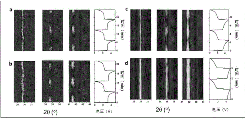
[0031] 4) Set the XRD equipment program, set the tu...

Embodiment 3

[0036] High temperature room temperature CV test

[0037] Step 1)-5) is the same as embodiment 2 step 1)-step 5);

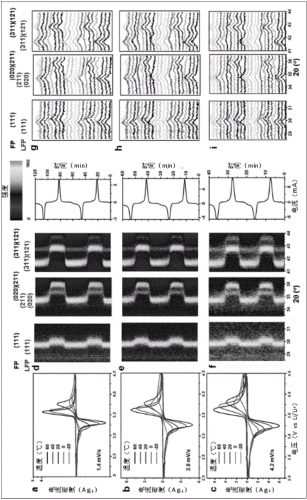
[0038] 6) Start the electrochemical test program, use the Chenhua electrochemical workstation to test the open circuit voltage of the battery to obtain the open circuit voltage v1, set the scanning voltage range to 2.4-4.5V, the initial voltage v1, and the scanning rate to 1.38mV / s, 2.7mV / s, 4.2mV / s. for three different scan rates. Sweep three cycles separately. Start the test to get the in-situ CV test results, such as image 3 shown.

[0039] Follow the steps to complete the in-situ XRD test of the high temperature CV charge and discharge of the material.


PUM


Abstract

The invention relates to a high-low-temperature in situ XRD analyzing and testing method for a lithium iron phosphate electrode material. The method comprises the steps of making an in situ test program obtain an XRD pattern of lithium iron phosphate in a high-temperature test mold or low-temperature test mold every thirty seconds by means of an X-ray light source of an ordinary laboratory, and setting the observation angle of a two-dimensional area detector XRD to be 17 degrees; conducting the process 1000 times to finish the XRD test program. According to the method, in situ XRD representation of the electrode material can be achieved without battery detachment, and research on influences of temperature variables on the electrode material is achieved at the same time. The method reveals that the low-temperature degradation property of the lithium iron phosphate electrode material is caused by lattice self-hold and reduction of ionic migration and diffusion rate under low temperature. Therefore, quick migration of lithium ions and increase of charge or discharge depth under high overpotential or strong polarization can still not be achieved.

Description

technical field [0001] The invention belongs to the technical field of nanometer materials and electrochemical in-situ analysis, and in particular relates to a high-low temperature in-situ XRD analysis and test method for lithium iron phosphate electrode materials. Background technique [0002] With the advancement of science and technology, the development of society and economy, and the rapid growth of population, the consumption of energy is also increasing. The depletion of non-renewable resources urgently requires renewable resources to play their role as substitutes. Use it effectively to realize its full potential. The existing traditional energy system can no longer meet the development needs of modern industry, agriculture, forestry, etc. Fuel and coal resources are not only non-renewable, but also produce a large amount of CO in the process of use and consumption. 2 , SO 2 and other harmful substances, causing serious environmental pollution. This has prompted p...

Claims


Application Information

Patent Timeline
IPC IPC(8): G01N23/20
CPCG01N23/20
Inventor 韩春华张国彬梅志文熊腾飞晏梦雨
Owner WUHAN UNIV OF TECH
Why Eureka
Try Eureka