Uplink and downlink wave beam shaping measure system and method

A beamforming and measurement system technology, applied in diversity/multi-antenna system, space transmit diversity, transmitter monitoring and other directions, can solve the problems of high test complexity, difficult amplitude and phase distribution, low test efficiency, etc., to eliminate the amplitude and phase Inconsistency, reducing test workload and test system complexity, and improving test efficiency

Inactive Publication Date: 2016-08-24
CHINA ACADEMY OF SPACE TECHNOLOGY
View PDF4 Cites 6 Cited by
  • Summary
  • Abstract
  • Description
  • Claims
  • Application Information

AI Technical Summary

Problems solved by technology

The measurement process requires frequent adjustment of the connection relationship of the cables, resulting in heavy workload and low test efficiency
However, if it is necessary to change the carrier frequency of the signal in the array element, the entire test work must be repeated again
As the number of array elements in the antenna array system continues to increase and the signal bandwidth of the array elements increases, it is becoming more and more difficult to measure the amplitude and phase distribution of the uplink and downlink beamforming systems using a vector network analyzer, and the test complexity is getting higher and higher.

Method used


Image

  • Uplink and downlink wave beam shaping measure system and method
  • Uplink and downlink wave beam shaping measure system and method
  • Uplink and downlink wave beam shaping measure system and method

Examples


Embodiment Construction

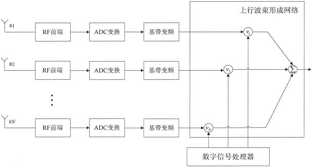
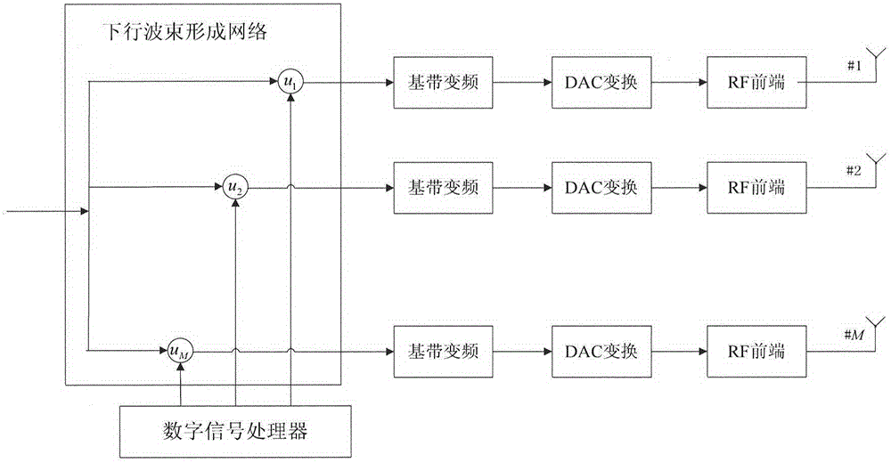
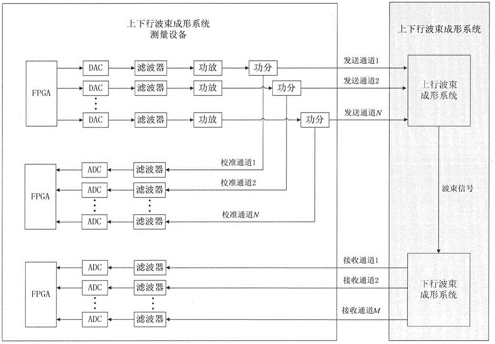
[0027] Attached below Figure 1-6 and specific embodiments to describe the present invention in detail. specifically, figure 1 is the system block diagram of the satellite uplink beamforming system, figure 2 is the system block diagram of the satellite downlink beamforming system, image 3 It is a schematic diagram of the system composition of the special measurement system for uplink and downlink beamforming, Figure 4 It is the flow chart of intermediate frequency digital signal processing at the sending end, Figure 5 It is the flow chart of intermediate frequency digital signal processing at the receiving end, Figure 6 It is the flow chart of IF digital signal processing of the verification network.

[0028] Such as image 3 As shown, the uplink and downlink beamforming measurement system involved in the present invention consists of three modules, namely, the transmitting end of the uplink beamforming system, the calibration network for the amplitude-phase consisten...


PUM


Abstract

The present invention provides an uplink and downlink wave beam shaping measure system and method. The uplink and downlink wave beam shaping measure system and method are able to measure and obtain the transmission matrix of a whole wave beam shaping system based on a software radio technology. The system comprises: a sending terminal of an uplink wave beam shaping system, wherein a sending channel is connected with a calibration channel of a sending channel amplitude consistency calibration network and the receiving channel of the feed source matrix of the uplink wave beam shaping network; the sending channel amplitude consistency calibration network employing an online calibration mode; and a downlink wave beam shaping system receiving terminal, wherein the receive channel is connected with the sending channel of the feed source matrix of the downlink wave beam shaping network. The uplink and downlink wave beam shaping measure system and method are able to ensure the accurate degree of the sending terminal to send multi-path sinusoidal signal amplitude phase information and perform the calibration of sending feed source signals and the test of the receiving feed source signals at the same time so as to improve the test efficiency of the test system and effectively reduce the test workload and the test system complexity.

Description

technical field [0001] The invention belongs to the field of digital signal processing, and relates to software radio technology, in particular to a dedicated measurement scheme for uplink and downlink beamforming based on software radio methods, and more specifically, to a measurement system and method for uplink and downlink beamforming for software radio technology. , a one-shot measurement to obtain the transfer matrix of the complete beamforming system. Background technique [0002] The antenna array is composed of a large number of array units (referred to as "array elements"), each array element is located in a different position in space, and forms an array according to certain rules. Compared with the unit antenna, the antenna array can effectively enhance the directivity of the antenna and increase the antenna gain at the same time. The core technology of the array antenna is beam forming (Beam-Forming, hereinafter referred to as BF) [0003] Beamforming technolo...

Claims


Application Information

Patent Timeline
Patent Type & Authority Applications(China)
IPC IPC(8): H04B17/12H04B17/24H04B7/04
Inventor 周慧王帅吴越郭宇琨林玉洁郝时光
Owner CHINA ACADEMY OF SPACE TECHNOLOGY
Why Eureka
Try Eureka