
Rock debris drying treatment and slurry purification system

A technology for mud purification and drying treatment, which is applied in the fields of sludge treatment, dewatering/drying/concentrated sludge treatment, water/sludge/sewage treatment, etc. Standard treatment, difficulty in transporting cuttings, etc., to achieve the effect of small footprint, high use efficiency, and saving drilling costs

Inactive Publication Date: 2016-09-07
范广潜
View PDF9 Cites 7 Cited by
  • Summary
  • Abstract
  • Description
  • Claims
  • Application Information

AI Technical Summary

Problems solved by technology

[0005] The existing cuttings conveying equipment has many difficulties in conveying cuttings to a higher orientation, and it is also difficult to meet the high standard treatment of cuttings in the later stage
If a concrete pump is used for transportation, not only the cost is too high, but also the amount of cuttings on site is too small to meet the working conditions of the concrete pump

Method used


Image

  • Rock debris drying treatment and slurry purification system
  • Rock debris drying treatment and slurry purification system
  • Rock debris drying treatment and slurry purification system

Examples


Embodiment 1

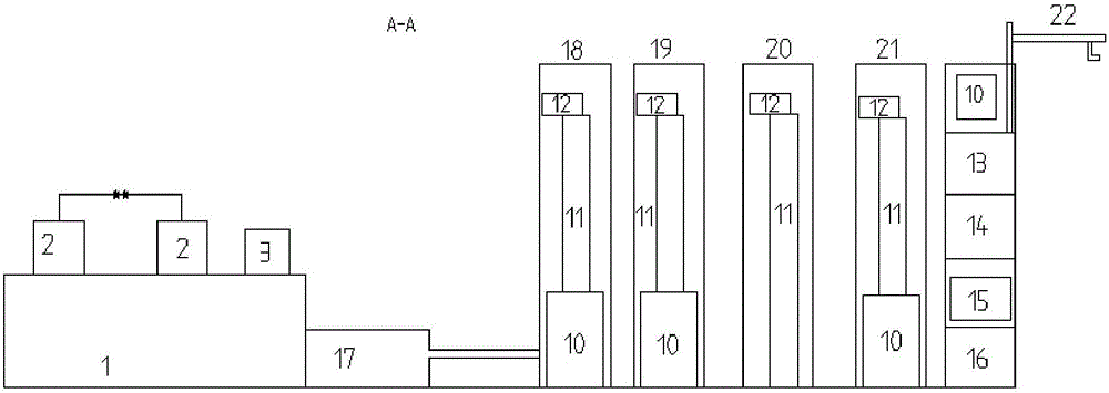
[0086] Such as Figure 1-4 As shown, the cuttings drying treatment mud purification system provided by this embodiment includes a primary treatment mud tank, a cuttings pump, a sand removal and mud removal integrated machine, a cuttings tank, a dryer and an air heater;

[0087] The cuttings pump is connected to the primary treatment mud tank, the primary treatment mud tank is connected to the cuttings tank through the integrated desanding and desilting machine, the cuttings tank is connected to the dryer, the dryer is connected to the air heater, and the air heater is connected to the exhaust pipe of the diesel engine;

[0088] The mud returned from the wellhead is transported to the primary treatment mud tank through the cuttings pump. After the primary treatment is carried out in the primary treatment mud tank, the mud is transferred to the cuttings tank through the integrated desanding and silting machine, and then sent from the cuttings tank to the dryer At the same time, the w...


PUM

PropertyMeasurementUnit
aspect ratioaaaaaaaaaa

Abstract

The invention relates to the technical field of rock debris treating equipment, in particular to a rock debris drying treatment and slurry purification system. The rock debris drying treatment and slurry purification system comprises a primary treatment slurry tank, a rock debris pump, an integrated sand and silt removing machine, a rock debris tank, a drying machine and an air heater, wherein the rock debris pump is connected with the primary treatment slurry tank, the primary treatment slurry tank is connected with the rock debris tank through the integrated sand and silt removing machine, the rock debris tank is connected with the drying machine, the drying machine is connected with the air heater, exhaust of a diesel engine enters the air heater, the rock debris pump includes an air compression component and a rock debris conveying component, the rock debris conveying component includes a screw rod conveyor, a power source, a rock debris inlet and a conveying outlet, the rock debris inlet and the conveying outlet are arranged on the screw rod conveyor, a rock debris dropping chamber is arranged below the conveying outlet, and the air compression component is communicated with the rock debris dropping chamber to provide high-speed air flow and output dropping rock debris at the conveying outlet at a high speed. The rock debris drying treatment and slurry purification system according to the invention has the advantages of small occupation, higher slurry use efficiency, more energy conservation and environmental protection.

Description

Technical field [0001] The invention relates to the technical field of cuttings processing equipment, in particular to a mud purification system for cutting cuttings drying treatment. Background technique [0002] Due to the continuous growth of construction engineering, bridge pile foundation engineering, underground tunnel shield engineering and oil drilling engineering, the output of mud from the equipment is increasing. The mud will be mixed with various chemical substances. If it is not treated If it flows into the land, it will surely cause various ecological problems, leading to more serious environmental pollution. [0003] With the continuous enhancement of modern society’s awareness of civilization and environmental protection, more and more attention has been paid to environmental problems brought about by projects in various fields. For the ecological problems of mud mixed with chemical pollutants, mud treatment technology and related mechanical equipment have also The...

Claims


Application Information

Patent Timeline
Patent Type & Authority Applications(China)
IPC IPC(8): C02F11/00C02F11/12C02F11/14C02F11/16E21B21/06B65G33/00B65G53/16
CPCC02F11/00B65G33/00B65G53/16C02F11/127C02F11/14C02F11/16E21B21/066
Inventor 范广潜
Owner 范广潜
Learn More