Composite beam type bridge floor continuation device and bridge floor continuation method applied in hollow slab girder bridges

A technology of hollow slab girders and composite beams, which is applied in bridges, bridge parts, bridge construction, etc., can solve problems affecting bridge durability and ride comfort, poor durability of unbonded materials, and failure to achieve unbonded, etc., to achieve Prevention of water seepage and erosion of concrete, easy factory processing, and prevention of water erosion and corrosion damage

Active Publication Date: 2016-09-07
ZHEJIANG UNIV
View PDF5 Cites 9 Cited by
  • Summary
  • Abstract
  • Description
  • Claims
  • Application Information

AI Technical Summary

Problems solved by technology

In theory, there is no bond between the connecting steel bar and the continuous concrete of the bridge deck, so the tensile force on the connecting steel bar cannot be transmitted to the concrete, but due to poor construction and poor durability of unbonded materials, it is actually impossible Achieve "non-stick" effect
The tensile force transmitted to the continuou

Method used


Image

  • Composite beam type bridge floor continuation device and bridge floor continuation method applied in hollow slab girder bridges
  • Composite beam type bridge floor continuation device and bridge floor continuation method applied in hollow slab girder bridges
  • Composite beam type bridge floor continuation device and bridge floor continuation method applied in hollow slab girder bridges

Examples


Embodiment 1

[0044] Embodiment 1, bridge deck continuous device.

[0045] Refer to attached Figure 3-11 .

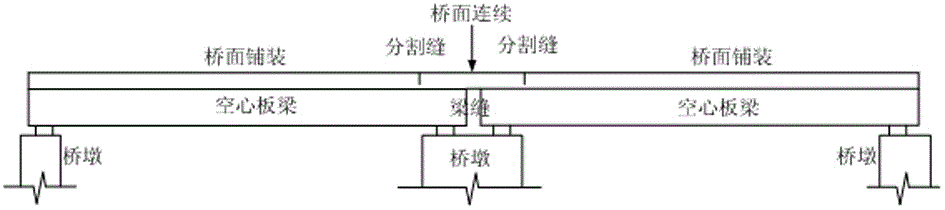
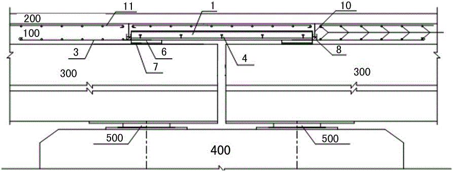
[0046] The bridge deck continuous device of the present invention is arranged in the bridge deck pavement reinforced concrete layer 100, the upper layer of the bridge deck pavement reinforced concrete layer 100 is the bridge deck pavement asphalt concrete layer 200, the bridge deck continuous device of the present invention is arranged on the hollow beam On the upper surface of the plate 300, the number 400 in the figure is a bridge pier, and the number 500 is a support.

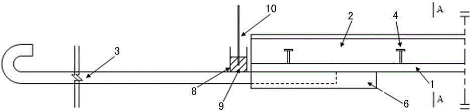
[0047] The bridge deck continuous device of the present invention comprises steel plate standard section 1, and steel plate standard section 1 adopts 8cm thick steel plate as basic material, considers the convenience of transportation and construction, according to the width of main girder girder of commonly used hollow slab girder bridge, is processed into horizontal length at factory Steel plate standard secti...

Embodiment 2

[0054] Embodiment 2, bridge deck continuous method.

[0055] Refer to attached Figure 3-11 .

[0056] The bridge deck continuous method of the present invention refers to the specific steps of applying the bridge deck continuous device of embodiment 1 to the hollow slab girder bridge, and the bridge deck continuous method can realize the continuous bridge deck of embodiment 1 on the hollow slab girder bridge device, the bridge deck continuous method comprises the following steps:

[0057] 1) The steel plate standard section 1 of the bridge deck continuous device is prefabricated in the factory, including T-shaped ribs 2 and shear nails 4 composed of 5 mm thick steel plates welded on 8 mm thick steel plates to improve the overall rigidity of the structure and strengthen the connection with concrete Then stick the F4 plate 6 on the bottom of both ends of the steel plate. When pasting the F4 plate, the side used for pasting is sodiumized first, and then glued to the bottom edg...

Embodiment 3

[0064] Embodiment 3, finite element analysis of bridge deck continuous device.

[0065] Refer to attached Figure 12 . The simulation of the device of the present invention adopts the large-scale general finite element program ABAQUS 6.12. In addition to the fine simulation geometric model, the distribution and material properties of the steel bars are also simulated strictly according to the design conditions. The simulation process consists of two steps:

[0066] (1) Establish the finite element simulation models of the continuous tie-rod bridge deck and the continuous steel-concrete composite beam deck respectively.

[0067] (2) By applying vehicle loads and temperature effects, simulating the actual bridge loading conditions, and comparing the force calculation results of two types of bridge deck continuous concrete, the effectiveness of the invention in preventing concrete cracking is demonstrated.

[0068] The calculation results of the continuous concrete stress of t...


PUM


Abstract

The invention provides a composite beam type bridge floor continuation device applied in hollow slab girder bridges. The device comprises a prefabricated steel plate standard segment with T-shaped ribs and F4 plates; the bottom of the steel plate standard segment is provided with longitudinal straight ribs welded at a construction site; the steel plate standard segment and the longitudinal straight ribs are supported on a cement mortar screed coat cast in situ on a hollow slab girder through the F4 plates; two sides of the steel plate standard segment are provided with stainless steel U-shaped drainage chutes; oil immersed cork strips and stainless steel plates are embedded in the U-shaped drainage chutes. The invention also provides a composite beam type bridge floor continuation method applied in hollow slab girder bridges. By means of the device and method, concrete cracking can be effectively prevented, and seepage water is discharged along two sides of the bridge to prevent erosion.

Description

technical field [0001] The invention relates to a bridge deck continuous device and a bridge deck continuous method of a hollow slab girder bridge. Background technique [0002] Hollow slab girder bridge is one of the earliest and most widely used small and medium-span bridge types in modern bridge construction, and has distinctive force and construction characteristics. First of all, it is a statically determinate structure with simple stress and convenient construction. The structural size can be designed as standard width and span, and the efficiency of bridge construction can be improved through large-scale prefabrication. No secondary stress will be generated under tension and prestressing conditions; in addition, for multi-span simply supported hollow slab girder bridges, in order to reduce the number of expansion joints on the bridge deck, improve the ride comfort and the service life of the bridge, the " bridge deck continuous” design method ( figure 1 ), combine m...

Claims


Application Information

Patent Timeline
IPC IPC(8): E01D2/00E01D19/12E01D19/08E01D21/00
CPCE01D2/00E01D19/086E01D19/125E01D21/00
Inventor 申永刚王城泉谢旭张仪萍
Owner ZHEJIANG UNIV
Why Eureka
Try Eureka