
Method for designing and forming stiffness-controllable bone tumor defect repair implant

A molding method and bone tumor technology, applied in design optimization/simulation, calculation, image data processing, etc., can solve the problems of bone loss, prosthesis loosening, brittle texture, etc. The effect of incidence

Inactive Publication Date: 2016-09-07
SOUTHERN MEDICAL UNIVERSITY
View PDF6 Cites 32 Cited by
  • Summary
  • Abstract
  • Description
  • Claims
  • Application Information

AI Technical Summary

Problems solved by technology

[0003] At present, most of the tumor-type prostheses used in clinical practice are mostly surface-polished structures, which are not conducive to the growth of surrounding tissues and affect osseointegration, and the prosthesis will loosen over time
Some scholars have proposed to fill the interface between the prosthesis and the surrounding bone tissue with bone cement, but this method is not conducive to the removal and revision of the prosthesis in the later stage; in addition, there are implants with porous designs on the market, although they create a favorable microenvironment for osseointegration , but because of its standard and standardized mass production, it is difficult to meet the reconstruction requirements of different types of defects in patients, and it is easy to cause a large amount of bone loss
At present, the stiffness of most metal implanted prostheses is far greater than the elastic modulus of human bone tissue, which is easy to cause stress shielding effect and lead to fatigue fracture of the prosthesis, while biological materials such as hydroxyapatite and calcium sulfate have excellent biological properties. Compatibility and high affinity with protein molecules, but its texture is brittle, poor toughness, low strength, bending strength and fracture toughness indicators are difficult to meet the requirements of mechanical stability

Method used


Image

  • Method for designing and forming stiffness-controllable bone tumor defect repair implant
  • Method for designing and forming stiffness-controllable bone tumor defect repair implant
  • Method for designing and forming stiffness-controllable bone tumor defect repair implant

Examples


Embodiment Construction

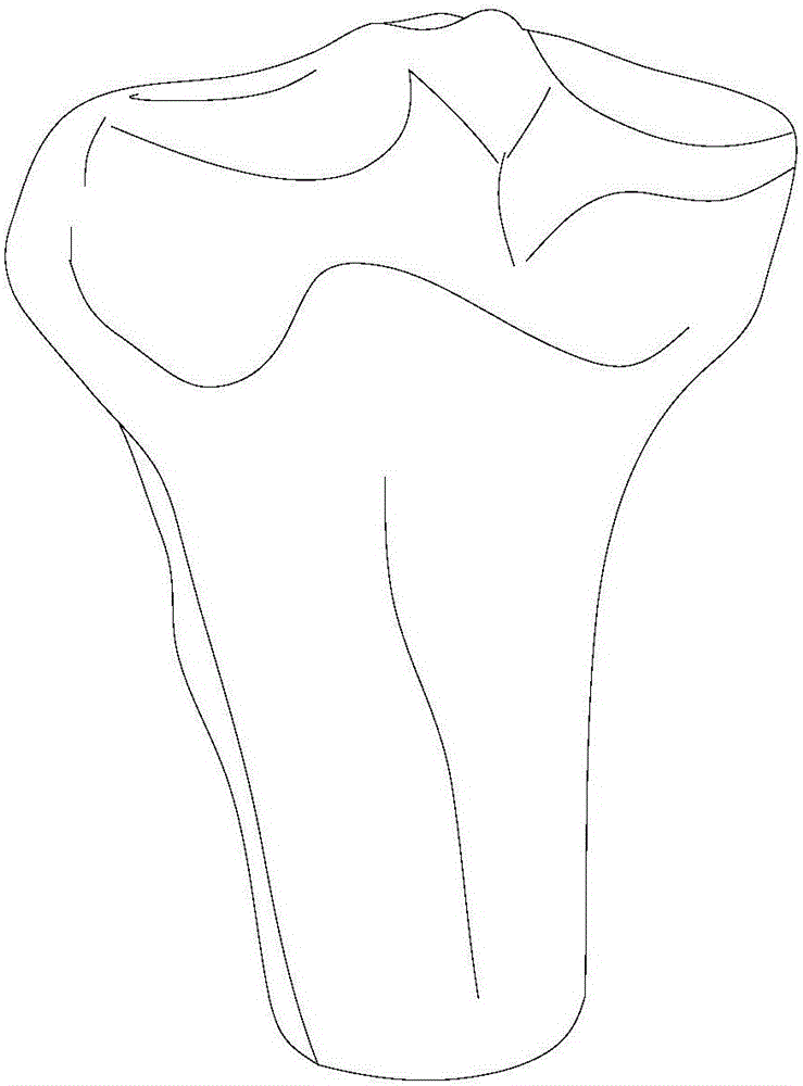
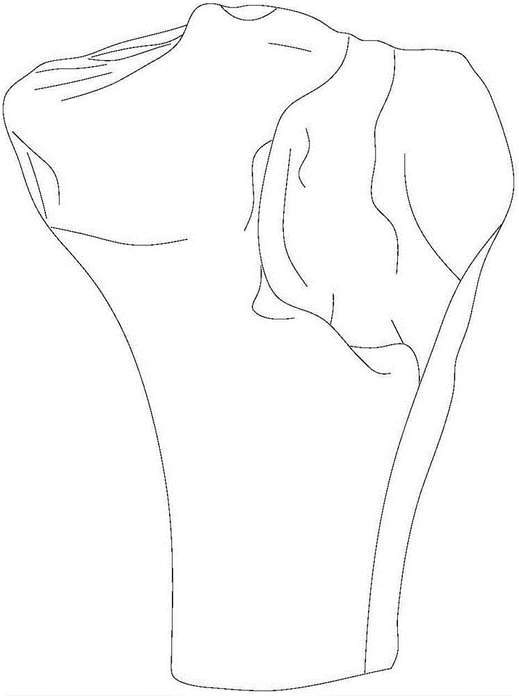
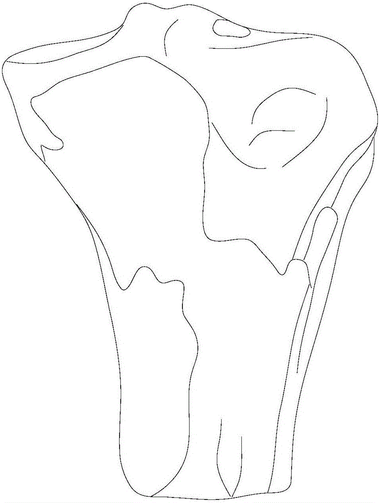
[0023] Such as Figure 1-Figure 5 As shown, a stiffness-controllable bone tumor defect repair implant design and molding method, including the following steps:

[0024] 1) Image data collection and preprocessing: 64-slice spiral CT scanning is performed on the affected side and the corresponding healthy side, and the original tomographic image data of the target part is obtained in Dicom format, and automatically numbered and sorted, and then the original CT image is eliminated by the median filter method. And salt and pepper noise, then use Gauss-Laplace transform to denoise to find the second-order derivative vector, use the zero-crossing point of the second-order derivative to determine and protect the signal edge, which is beneficial to the later image segmentation;

[0025] 2) Reconstruction of the 3D digital model after resection of the ipsilateral tumor and repair of mirror image defects: Import the preprocessed Dicom data into the medical modeling software Mimics, dete...


PUM


Abstract

The invention discloses a method for designing and forming a stiffness-controllable bone tumor defect repair implant. The method comprises the following steps of acquiring and preprocessing image data; performing reverse image fusion and registration, and constructing an accurate curve surface materialized repair body model; carrying out parallel finite element analysis and optimization on a porous design scheme by a microscopic porous scheme design; and importing the model into a 3D printing system for printing forming. According to the method, a personalized porous structure, mechanical optimization design and 3D printing forming of a post-bone tumor excision defect area reconstruction repair body are realized in combination with digital modeling, finite element analysis and medical 3D printing technologies according to a symmetric characteristic of a human body structure morphology, so that the reconstruction effect of an individualized anatomic morphology and the design forming efficiency of the repair body are improved, the time and material costs are reduced, the mechanical properties and the bone integration microenvironment after reconstruction are better optimized, and the bone growth repair of a bone defect area is facilitated.

Description

technical field [0001] The invention relates to a design and molding method of a bone tumor defect repair implant with controllable stiffness. Background technique [0002] The refined anatomical reconstruction of bone defects after bone tumor resection has always been a difficult problem in the medical field. Autologous bone grafting is an ideal material and method for repairing and reconstructing bone defects, but there are increased surgical trauma, complications such as infection and pain at the bone harvesting site, and the existence of The amount of autologous bone is limited, and it is difficult to meet the requirements of large-segment bone transplantation. However, traditional prostheses cannot meet the reconstruction requirements of different types of defects due to their own standardized, mass-produced and serialized production, and the patient's anatomical parameters and individual characteristics in the body, making it difficult to optimize the interaction betwe...

Claims


Application Information

Patent Timeline
IPC IPC(8): G06F17/50G06T17/00B22F3/00B22F10/85
CPCG06T17/00B22F3/00G06F30/23
Inventor 黄文华谢普生欧阳汉斌
Owner SOUTHERN MEDICAL UNIVERSITY
Learn More