A kind of automatic assembly mechanism and working method of automobile inductance

An assembly mechanism and working method technology, applied in the direction of inductors, fixed inductors, fixed signal inductors, etc., can solve problems such as unsatisfactory effects, low efficiency, and difficult quality assurance, and achieve a high degree of assembly automation and avoid efficiency Low, easy-to-operate effect

Active Publication Date: 2017-12-08
上海奇开电器有限公司
View PDF5 Cites 0 Cited by
  • Summary
  • Abstract
  • Description
  • Claims
  • Application Information

AI Technical Summary

Problems solved by technology

[0004] The process of assembling the coil and the magnetic core into a finished product is usually completed manually by workers, that is, inserting the magnetic core into the coil after dispensing glue on the magnetic core. Difficult to guarantee, vary from person to person;
[0005] Of course there are also ways to use automated assembly, ie, such as figure 1 As shown in the figure, the coils are sorted and positioned using a vibrating plate through a vibrating screen, and then the magnetic core with glue is used as the active part, and the coil is used as the passive part, and the magnetic core is moved to the assembly entry point and inserted into the coil to complete the assembly; this use The vibration plate is assembled in a complex mechanical structure. During the working process, there are problems such as coil deformation, chuck, wear and pin string coil inner hole guidance, and the effect is not satisfactory.

Method used


Image

  • A kind of automatic assembly mechanism and working method of automobile inductance
  • A kind of automatic assembly mechanism and working method of automobile inductance
  • A kind of automatic assembly mechanism and working method of automobile inductance

Examples


Embodiment 1

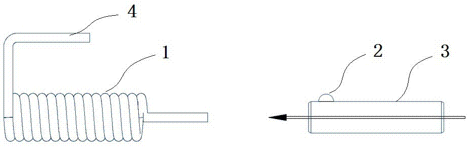
[0031] Example 1: Such as figure 2 , 6 As shown in 7, this embodiment specifically relates to an automated assembly mechanism for automobile inductors and a working method thereof. The automated assembly mechanism is mainly used to assemble the coil 1 with the pin 4 and the magnetic core 3 to obtain the automobile inductor.

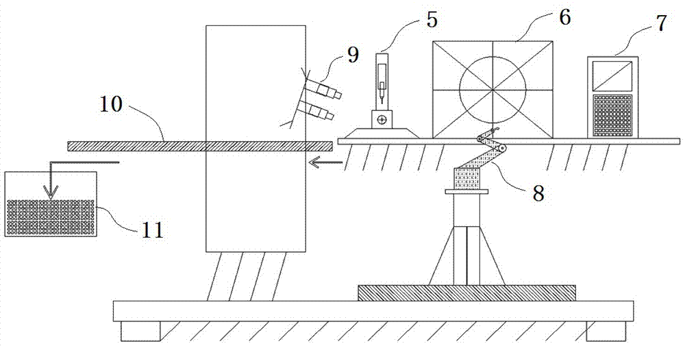
[0032] Such as Figure 2-7 As shown, the automated assembly mechanism in this embodiment mainly includes a winding forming machine 6, a coil clamping device 8, an assembly head 5, a central control system 7, an image detection device 9, a conveyor belt 10, and a finished product box 11, among which:

[0033] The winding forming machine 6 is a coreless winding forming machine, it can also be a core winding forming machine or a special winding forming machine, which is used to wind and produce the coil 1, and the tail end of the coil 1 has a bending point toward its beginning. Pin 4, pin 4 is parallel to the body of coil 1;

[0034] The coil clamping device 8 is ...

Embodiment 2

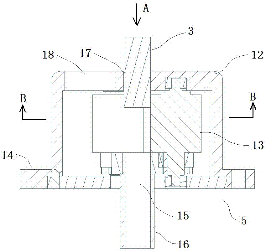
[0047] Example 2: Such as Figure 2-7 As shown, this embodiment specifically relates to an automated assembly mechanism for automotive inductors and its working method. The difference between the automated assembly mechanism and the automated assembly mechanism in Embodiment 1 is that the rubber wheel 13 has a spiral function, and the magnetic core clamps The wheel set can rotate and advance the magnetic core 3 while clamping the magnetic core 3, and the rest of the structure is the same.

[0048] Such as Figure 2-7 As shown, the working method of the automotive inductor automatic assembly mechanism in this embodiment includes the following steps:

[0049] (1) Winding forming machine 6 produces coil 1 with pin 4;

[0050] (2) The coil clamping device 8 travels to the top of the winding forming machine 6 and clamps the end position of the coil 1, and then moves the coil 1 to directly above the assembly head 5, that is, directly above the core hole 17;

[0051] (3) Both the coil 1 and ...

Embodiment 3

[0056] Example 3: Such as figure 2 , 8 , 9, and 10, this embodiment specifically relates to an automated assembly mechanism for automotive inductors and its working method. The automated assembly mechanism is mainly used to assemble the leadless coil 1 with the magnetic core 3 to obtain automotive inductors. .

[0057] The difference between the automated assembly mechanism in this embodiment and the assembly mechanism in Example 1 is that the assembly head base 5 is an external-rotation assembly head with no pin relief holes on it, which is suitable for a leadless coil with a magnetic core. The assembling between the room; the rest of the structure and specific working methods are the same as those described in Embodiment 1, and will not be repeated here.


PUM


Abstract

The invention discloses an automatic assembling mechanism for an automobile inductor, and an operating method of the automatic assembling mechanism, and relates to assembling between coils and magnetic cores. The automatic assembling mechanism is characterized by comprising a coil clamping apparatus and an assembling headstock, wherein the assembling headstock comprises a base, a magnetic core clamping wheel group which is perpendicularly arranged on the base, and a cover body for packaging the magnetic core clamping wheel group; a magnetic-core passing-through hole is formed in the upper end plane of the cover body; the magnetic core clamping wheel group comprises at least three adhesive wheels which are distributed at intervals along the magnetic-core passing-through hole. The automatic assembling mechanism has the advantages of simple structure, high assembling automatic degree, less working procedures, convenient control and operation, and capabilities of improving the assembling efficiency and the mass and lowering the production cost, avoiding the problems of low efficiency and difficulty in ensuring the quality existing in the conventional manual assembling of the automobile inductors, as well as overcoming the shortcomings of deformation, clamping and the like existing in the conventional coil assembling by adopting a vibrating plate structure.

Description

Technical field [0001] The invention belongs to the field of assembly technology, and specifically relates to an automatic assembly mechanism for automotive inductors and a working method thereof. Background technique [0002] The shape of automobile inductors is complex and there are many varieties. It is applied to EMC anti-interference of various automobile motors. At present, its production method is mainly divided into the following two major steps: (1) winding and forming of the coil; (2) coating the coil and dots with The magnetic core of the glue is assembled into a finished car inductor. among them: [0003] At present, the coil winding forming processing equipment mainly includes core forming and coreless forming, which are relatively high in automation; [0004] The process of assembling the coil and the magnetic core into a finished product is usually done manually by workers, that is, inserting the magnetic core into the coil after dispensing glue on the magnetic core....

Claims


Application Information

Patent Timeline
Patent Type & Authority Patents(China)
IPC IPC(8): H01F37/00H01F41/00H01F41/066
CPCH01F37/00H01F41/00
Inventor 糜荣南刘兵徐鹏孙奇伟
Owner 上海奇开电器有限公司
Why Eureka
Try Eureka