Integrated automatic control hydraulic servomotor

An oil motor and oil tank technology, applied in the direction of fluid pressure actuation devices, fluid pressure actuation system components, mechanical equipment, etc., can solve the problems of reducing the life of hydraulic oil, increasing the amount of maintenance, and high maintenance requirements, so as to reduce the occurrence of failures probability, reduce design complexity, and simplify the effect of equipment wiring

Inactive Publication Date: 2016-09-14
XIAN QIANGYUAN ELECTRIC APP CO LTD
View PDF6 Cites 3 Cited by
  • Summary
  • Abstract
  • Description
  • Claims
  • Application Information

AI Technical Summary

Problems solved by technology

[0006] 2. The failure rate of the oil motor in the traditional system is high. The reason is that the electro-hydraulic servo valve is very sensitive to the cleanliness requirements of the hydraulic medium. If the cleanliness decreases, the electro-hydraulic servo valve will fail, resulting in the failure of the oil motor control function;
[0007] 3. The traditional system has long pipelines, many interfaces and joints, and the laying area of ​​multiple components is large, which is prone to hydraulic medium leakage, involving a large area
[0009] 1. The hydraulic circuit is not isolated from the outside air. In the case of long-term contact with the air, the hydraulic oil will oxidize and deteriorate, which reduces the life of the hydraulic oil and increases the amount of maintenance; 2. Only includes hydraulic and mechanical devices, and cannot be intelligentized Automatic control; 3. On-site professionals are required for maintenance, and the maintenance requirements are high. Professionals are not required during normal operation on site, resulting in waste of human resources; 4. When a fault occurs, timely warning cannot be given, which will cause greater losses on site

Method used


Image

  • Integrated automatic control hydraulic servomotor

Examples


Embodiment Construction

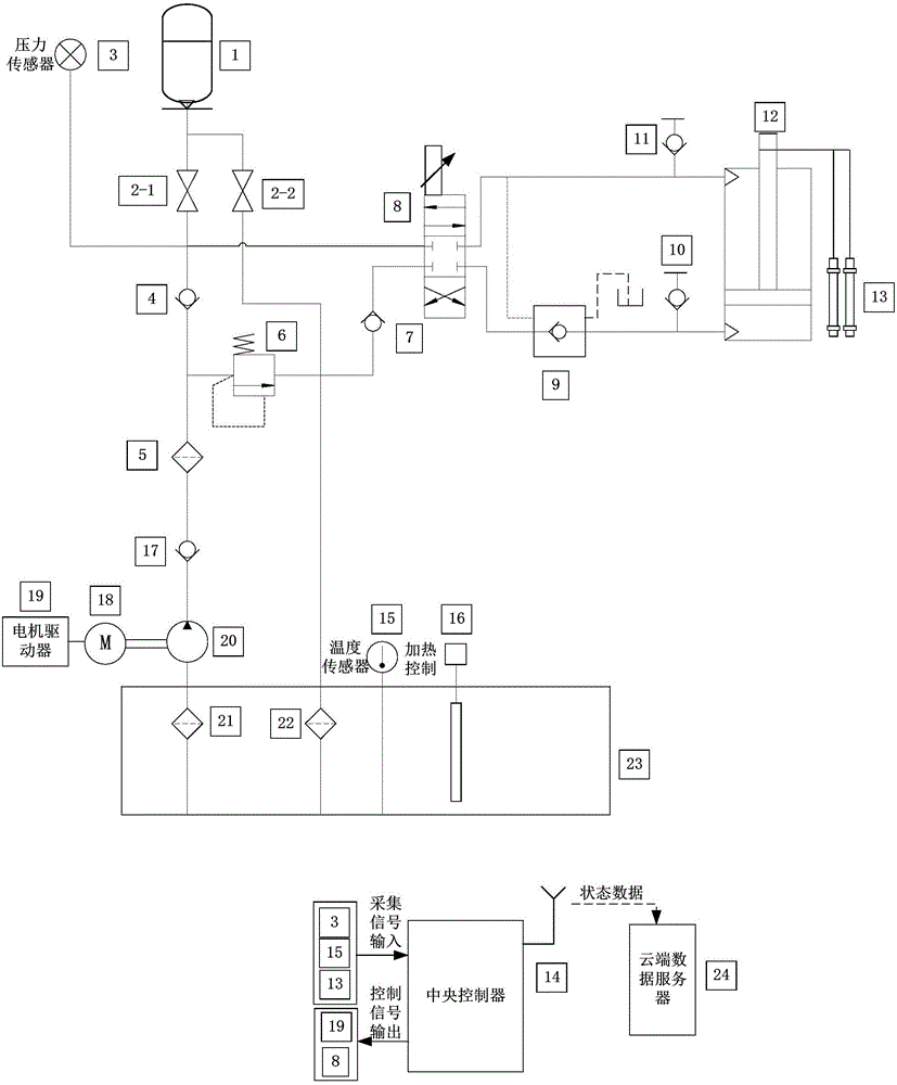
[0026] The present invention will be described in further detail below in conjunction with the accompanying drawings.

[0027] see figure 1 , the present invention structurally includes an oil tank 23 and an oil supply pipeline and an oil return pipeline connected to the oil tank 23 through an oil supply filter 21 and an oil return filter 22 respectively, and the oil supply pipeline is respectively connected to the accumulator 1 through an oil pump 20 And the hydraulic cylinder 12, the accumulator 1 is connected to the oil supply pipeline through the normally open oil inlet ball valve 2-1, and is connected to the oil return pipeline through the normally closed oil outlet ball valve 2-2. The oil pump 20 is connected with a motor 18 for driving its action. On the oil supply pipeline at the outlet of the oil pump 20, a check valve 17, a filter 5, and a check valve 4 for preventing oil supply backfilling when the oil pump 20 stops are arranged in sequence. The oil cylinder 12 is ...


PUM


Abstract

An integrated automatic control hydraulic servomotor comprises an oil tank, an oil supply pipeline and an oil return pipeline, the oil supply pipeline passing a supply oil filter and the oil return pipeline passing a return oil filter are connected with the oil tank. The oil supply pipeline is connected with an energy accumulator and a hydraulic oil cylinder through an oil pump. The oil pump is connected with a motor used for driving the oil pump to act. A temperature sensor used for collecting the oil temperature and a heating control device used for temperature rising of oil liquid are arranged on the oil tank. A cylinder block of the hydraulic oil cylinder is connected with a pressure sensor used for collecting pressure in the hydraulic oil cylinder. A position sensor is connected to an output shaft of the hydraulic oil cylinder. The temperature sensor, the pressure sensor and the position sensor are all connected with a center controller. The signal output end of the center controller is connected with a motor driver and an electro-hydraulic change-over valve. The motor driver is connected with the motor in a control manner. The electro-hydraulic change-over valve is connected with the hydraulic oil cylinder in a control manner. By the adoption of the integrated automatic control hydraulic servomotor, site construction and maintenance are convenient, integrated integral mounting is conducted according to the mounting position, the requirement on site construction and maintenance is lowered, the fault probability is reduced, and automatic control can be achieved.

Description

technical field [0001] The invention relates to the field of hydraulic drive, in particular to an integrated automatic control oil motor capable of linear drive or rotary drive. By receiving standard signal input, the position and load are closed-loop controlled to reach the input set value. Background technique [0002] The traditional hydraulic servo system includes 1 hydraulic oil source, 2 to 4 hydraulic actuators (also known as oil motors, two types of functions: sub-valve and main valve), filter device, energy storage device, regeneration device and temperature control device , the components are connected by pipelines. Among them, the hydraulic oil source in the hydraulic servo system provides hydraulic power for the hydraulic actuator, and the hydraulic power input to the oil motor is converted into the displacement movement output of the piston rod to control the steam valve of the steam turbine unit. The energy storage device absorbs, stores and supplements the hy...

Claims


Application Information

Patent Timeline
IPC IPC(8): F15B1/02F15B21/08
CPCF15B1/024F15B21/08
Inventor 罗永超马茗方红亮
Owner XIAN QIANGYUAN ELECTRIC APP CO LTD
Why Eureka
Try Eureka