Pyroelectric detector

A pyroelectric detector and resistance technology, applied in the direction of electrical radiation detectors, etc., can solve the problems of small signal amplitude, easy to be interfered by radio frequency radiation, low response signal, etc., and achieve accurate response, good reliability and performance. stable effect

Inactive Publication Date: 2016-09-14
UNIV OF ELECTRONICS SCI & TECH OF CHINA
View PDF7 Cites 3 Cited by
  • Summary
  • Abstract
  • Description
  • Claims
  • Application Information

AI Technical Summary

Problems solved by technology

[0003] At present, pyroelectric detectors have the disadvantages of small signal amplitude and are easily interfered by various heat sources and light sources, especially by radio frequency radiation.
Existing pyroelectric detector...

Method used


Image

  • Pyroelectric detector
  • Pyroelectric detector
  • Pyroelectric detector

Examples


Embodiment Construction

[0017] Preferred embodiments of the present invention are described in detail below in conjunction with accompanying drawings:

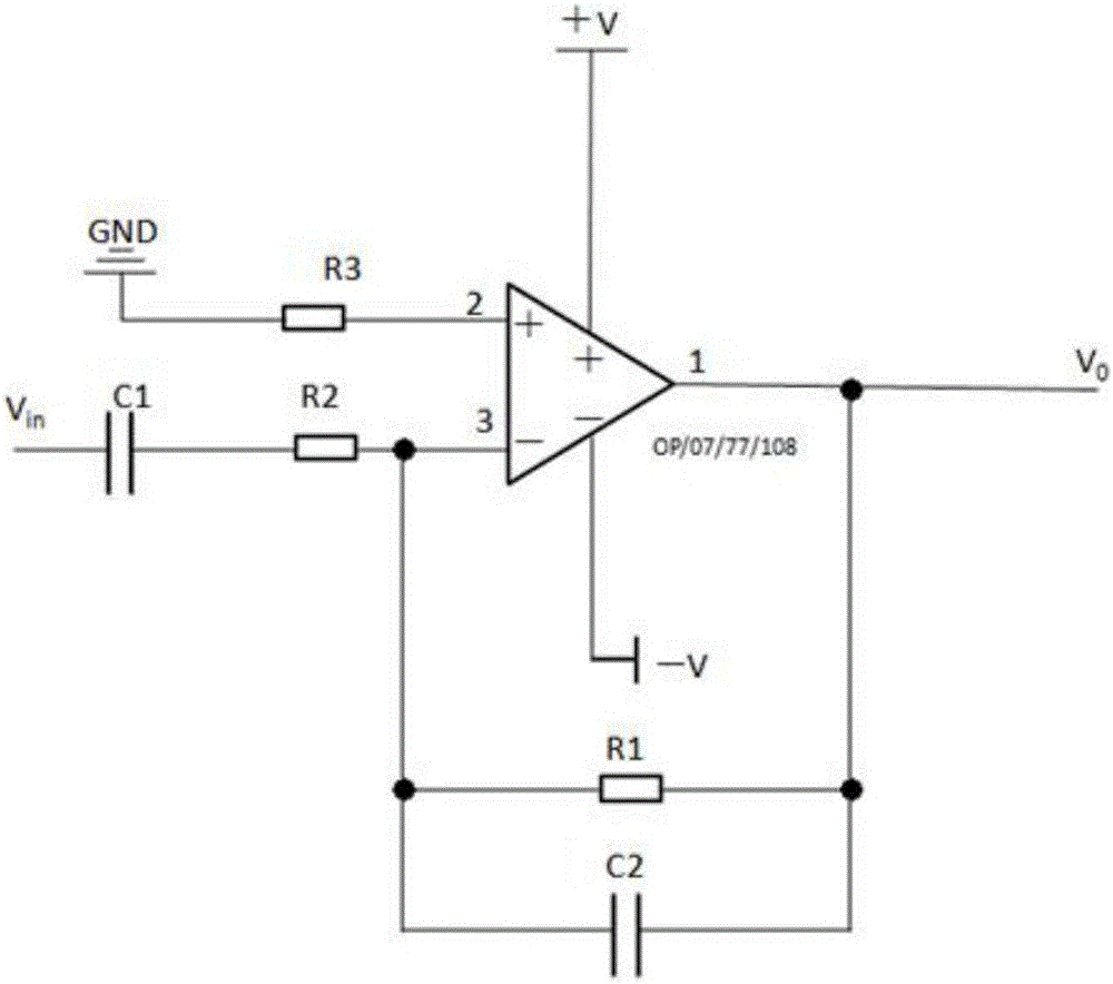
[0018] Such as figure 1 As shown, this figure is a schematic diagram of the signal processing circuit of the pyroelectric detector of the present invention. Input voltage signal V in Form the output voltage signal V after being processed by the signal processing circuit of the present invention o , the pyroelectric detector of the present invention includes an optical system, an infrared sensor unit, a signal processing circuit, and an output control device; it is characterized in that the signal processing circuit includes: an operational amplifier OP-07 / 77 / 108, a capacitor C 1 、C 2 , resistor R 1 , R 2 , R 3 . Raw signal by capacitor C 1 terminal input, the V 0 terminal output. Input the capacitor C of the original signal terminal 1 and resistor R 2 After being connected in series with the non-inverting input terminal 3 of the operation...


PUM

PropertyMeasurementUnit
Resistanceaaaaaaaaaa

Abstract

The invention, which belongs to the field of the electronic technology of the pyroelectric detector, discloses a pyroelectric detector comprising an optical system, an infrared sensor unit, a signal processing circuit, and an output control device. The pyroelectric detector is characterized in that the signal processing circuit consists of an operational amplifier, a capacitor C1, a capacitor C2, a resistor R1, a resistor R2, and a resistor R3; after the capacitor C1 and the resistor R2 that are inputted into an original signal terminal are connected in series, the serial unit is connected with an in-phase input terminal (3) of the operational amplifier; one end of the resistor R3 is grounded and the other end of the resistor R3 is connected with an inverting output terminal (2) of the operational amplifier; and the resistor R1 and the capacitor C2 are connected in parallel between the in-phase input terminal (3) of the operational amplifier and an output terminal (1). The power supply way of the operational amplifier is a voltage power supply way; and Vo is a signal processing output terminal. The pyroelectric detector has the following advantages: the performances are stable; reliability is high; detection signals with high responses and low noises can be detected and outputted without any error in various working environments; and large-scale industrial production can be realized.

Description

technical field [0001] The invention relates to the electronic technical field of pyroelectric detectors, in particular to a differential circuit applied to pyroelectric detectors. Background technique [0002] Pyroelectric detector is a kind of heat-sensitive infrared detector made by using the effect that the spontaneous polarization of pyroelectric material changes with temperature. At a constant temperature, the spontaneous polarization of pyroelectric materials is neutralized by charges in the bulk and surface adsorption. If the pyroelectric material is made into a parallel sheet whose surface is perpendicular to the polarization direction, when infrared radiation is incident on the surface of the sheet, the temperature of the sheet changes due to the absorption of radiation, and the distance and chain between dipoles in the pyroelectric material Angle changes, so that the polarization intensity changes. The neutralization charge cannot keep up with this change due to...

Claims


Application Information

Patent Timeline
IPC IPC(8): G01J5/34
CPCG01J5/34
Inventor 王涛梁志清伍浏权马振东刘子骥蒋亚东
Owner UNIV OF ELECTRONICS SCI & TECH OF CHINA
Why Eureka
Try Eureka