High-gain quasi-switch boost DC-DC converter

A quasi-switching step-up, DC-DC technology, applied in the field of high-gain quasi-switching step-up DC-DC converter circuit, can solve the problems of no longer applicable and small output voltage variation range, and achieve convenient control and output voltage gain High, simple circuit structure effect

Active Publication Date: 2016-09-14
SOUTH CHINA UNIV OF TECH
View PDF3 Cites 7 Cited by
  • Summary
  • Abstract
  • Description
  • Claims
  • Application Information

AI Technical Summary

Problems solved by technology

The switching boost converter SBI proposed in recent years has a small output voltage variation range. In the occasions of low voltage input and high voltage output, such as distributed energy grid-connected systems and fuel cell systems, the traditional SBI converter becomes no longer suitable. Be applicable

Method used


Image

  • High-gain quasi-switch boost DC-DC converter
  • High-gain quasi-switch boost DC-DC converter
  • High-gain quasi-switch boost DC-DC converter

Examples


Embodiment Construction

[0011] The technical solution of the present invention has been described in detail above, and the specific implementation of the present invention will be further described below in conjunction with the accompanying drawings.

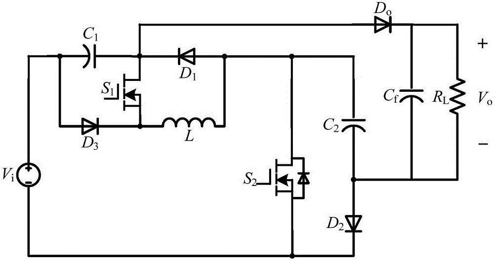
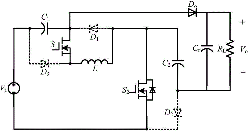
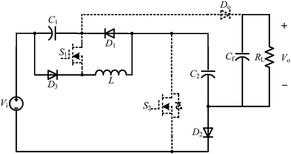
[0012] refer to figure 1 , a high-gain quasi-switch step-up DC-DC converter circuit according to the present invention, including a voltage source, composed of a first capacitor, a first diode, a first MOS transistor, a third diode and an inductor A two-terminal quasi-switch boost unit, a second MOS tube, a second capacitor, a second diode, and an output diode D o , the output filter capacitor C f and load R L . When the first MOS tube S 1 and the second MOS tube S 2 While conducting, the first diode D 1 , the second diode D 2 , the third diode D 3 are turned off; the voltage source V i with the first capacitor C 1 Charge and store energy together for the inductor L; at the same time, the voltage source V i , the first capacitance C 1 with ...


PUM


Abstract

The present invention provides a high-gain quasi-switch boost DC-DC converter circuit. The high-gain quasi-switch boost DC-DC converter circuit includes a voltage source, a two-end quasi-switch boost unit, a second metal-oxide semiconductor (MOS) transistor, a second capacitor, a second diode, an output diode, an output filter capacitor and a load. The two-end quasi-switch boost unit consists of a first capacitor, a first diode, a first MOS transistor, a third diode and an inductor. The whole circuit has a simple structure, combines single-stage boost characteristics of both the quasi-switch boost unit and a switch capacitor, and realizes expansion of an output voltage gain.

Description

technical field [0001] The invention relates to the technical field of power electronic circuits, in particular to a high-gain quasi-switch step-up DC-DC converter circuit. Background technique [0002] In fuel cell power generation and photovoltaic power generation, due to the low DC voltage provided by a single solar cell or a single fuel cell, it cannot meet the electricity demand of existing electrical equipment, nor can it meet the needs of grid connection. It is often necessary to combine multiple batteries connected in series to achieve the desired voltage. On the one hand, this method greatly reduces the reliability of the entire system, and on the other hand, it needs to solve the problem of series voltage equalization. For this reason, a high-gain DC-DC converter capable of converting low voltage to high voltage is required. The switching boost converter SBI proposed in recent years has a small output voltage variation range. In the occasions of low voltage input...

Claims


Application Information

Patent Timeline
Patent Type & Authority Applications(China)
IPC IPC(8): H02M3/158
CPCH02M3/158
Inventor 张波朱小全丘东元
Owner SOUTH CHINA UNIV OF TECH
Why Eureka
Try Eureka