
A brick-laying machine

A brick machine and wall-building technology, which is applied in the field of electromechanical, can solve personal safety problems, achieve the effects of reducing personal safety risks, solving the shortage of construction labor, and reducing labor

Active Publication Date: 2019-09-27
泉州台商投资区双艺商贸有限公司
View PDF5 Cites 0 Cited by
  • Summary
  • Abstract
  • Description
  • Claims
  • Application Information

AI Technical Summary

Problems solved by technology

In the face of this fast-growing construction industry, there is also an important safety issue. In some places, it is more likely to cause personal safety to build walls manually.

Method used


Image

  • A brick-laying machine
  • A brick-laying machine

Examples


Embodiment Construction

[0017] Further detailed description will now be made in conjunction with the accompanying drawings.

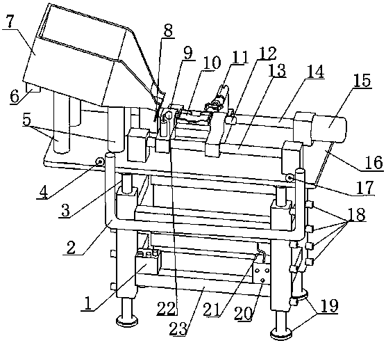
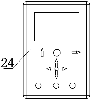
[0018] like figure 1 , figure 2 As shown, a brick laying machine includes: a hydraulic station 1, a U-shaped pipe 2, an upper telescopic hydraulic rod 3, a camera ①4, a spring column 5, a vibration motor 6, a funnel 7, a valve 8, a trolley 9, a turning plate 10, Robot 11, motor 12, polished rod 13, lead screw 14, stepping motor 15, top plate 16, camera 17. Hydraulic pipe interface 18, lower telescopic hydraulic rod 19, control electric box 20, wireless transceiver 21, camera 22. Rack 23, Remote control 24.

[0019] The main working principle of a brick-laying machine: first place the brick-laying machine in the place where the bricks need to be laid, and after placing it, adjust it through the upper telescopic hydraulic rod 3 and the lower telescopic hydraulic rod 19 of the frame. The horizontal position of the fuselage and the top plate 16 . Then put a certain number ...


PUM


Abstract

The invention discloses a wall brick building machine, belongs to the dynamo-electric field, and comprises a control system, a dolly, a turning disc, a manipulator, a screw rod, a polish rod, and a stepping motor; the turning disc is arranged on the upper portion of the dolly, used for loading bricks, and can horizontally and vertically turn; the manipulator is arranged on one side of the dolly; the dolly is connected with the screw rod and the polish rod; the screw rod is driven by the stepping motor to rotate, thus driving the dolly to move back and forth on the screw rod and the polish rod; the control system can control the dolly to accurately stop; when the dolly stops, the manipulator can grab the brick in the turning disc through rectangular openings on two sides of the turning disc, can accurately place the brick onto the building position, and can apply certain pressure on the newly placed brick, thus knocking the new brick to be flush with built bricks, and finishing wall building work. The beneficial effects are that the wall brick building machine can effectively solve the labor shortage problems in building industry, can mitigate worker laboring intensity, and can reduce worker personal safety risks in working.

Description

technical field [0001] The invention relates to the field of electromechanical, in particular to a brick-laying machine. Background technique [0002] With the rapid development of the construction industry, the market has a large demand for workers who build walls. At present, the existing workers in the market can no longer meet the needs of the construction industry. In the face of this fast-developing construction industry, there is also an important safety problem. In some places, it is more likely to cause personal safety when building walls manually. In order to solve the above problems, the present invention provides a wall laying machine. SUMMARY OF THE INVENTION [0003] In order to solve the above problems, the purpose of the present invention is to provide a wall laying machine. [0004] The concrete technical scheme adopted in the present invention is: [0005] The utility model relates to a brick laying machine, comprising a control system, a trolley, a tu...

Claims


Application Information

Patent Timeline
Patent Type & Authority Patents(China)
IPC IPC(8): E04G21/22
Inventor 不公告发明人
Owner 泉州台商投资区双艺商贸有限公司
Learn More