
A small differential high voltage output relay control box

A relay control box and output-type technology, applied in the direction of control/regulation systems, instruments, and adjustment of electrical variables, etc., can solve problems that do not meet the principles of low power consumption, high reliability, and energy saving, difficulty in realizing computer digitization, and inability to meet use requirements, etc. problem, to achieve the effect that the signal is not easy to attenuate, the assembly and debugging are convenient, and the weight is light

Active Publication Date: 2017-10-27
贵州振华群英电器有限公司(国营第八九一厂)
View PDF5 Cites 0 Cited by
  • Summary
  • Abstract
  • Description
  • Claims
  • Application Information

AI Technical Summary

Problems solved by technology

The existing relay control is mainly an integral milling structure, which is bulky and heavy, with weak load capacity and small insulation resistance, which cannot meet the requirements of aerospace, military ships, nuclear industry, armored weapons and other fields.
And the output current is 50A, the output voltage is 2000V, and the relay control box with the insulation resistance above 2000MΩ is currently unable to make the external dimension less than 120.5mm×48.5mm×83.5mm, the weight less than 500g, and the closed structure
At the same time, the traditional high-voltage power supply and distribution relay is an analog voltage-type control method. The signal attenuation is serious during long-distance control, the anti-interference ability is poor, and the power consumption is serious when working for a long time. consumption, high reliability, and energy saving principles, and analog voltage control is difficult to realize computer digitization

Method used


Image

  • A small differential high voltage output relay control box
  • A small differential high voltage output relay control box
  • A small differential high voltage output relay control box

Examples


Embodiment Construction

[0022] Embodiment of the invention

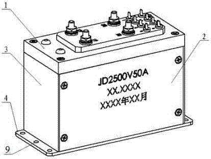
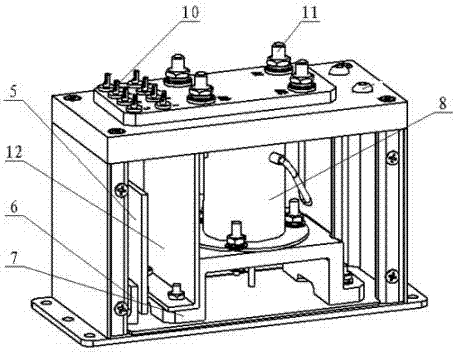
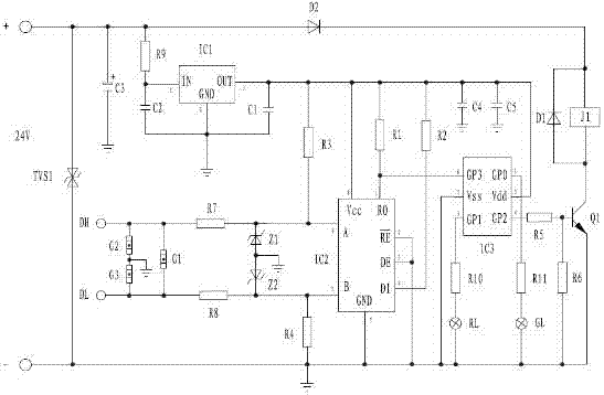
[0023] A small differential high voltage output relay control box, as attached Figure 1-3 As shown, the relay control box includes a base plate 4, the base plate 4 is provided with a side plate 2, and one side of the side plate 2 is provided with a cover plate 3 (the base plate 4, the side plate 2 and the cover plate 3 are all made of metal materials ), the top of the side plate 2 is provided with a wiring board assembly 1 made of polytetrafluoroethylene; the bottom plate 4 in the side plate 2 is provided with a circuit board support 6, and one side of the circuit board support 6 is provided with a relay Support 7 (circuit board support 6 and relay support 7 are all made of polytetrafluoroethylene material), described circuit board support 6 is connected with control circuit board 5, and the input terminal of control circuit board 5 is connected to the terminal block assembly 1 On the input terminal 10, the relay bracket 7 is connected wi...


PUM


Abstract

The invention discloses a small differential high-voltage output relay structure. The relay control box includes a bottom plate, a side plate, a cover plate and a wiring board assembly; the bottom plate in the side plate is provided with a circuit board support and a relay support , the circuit board bracket is connected with a control circuit board, and the relay bracket is connected with a relay; the circuit of the control circuit board includes an input power supply, a three-terminal voltage regulator circuit, a differential drive circuit, a spike suppression circuit, and a control signal anti-shake circuit , Relay drive circuit, power output circuit and status indication circuit. The present invention has the advantages of small size, light weight, strong load capacity, excellent reliability, high insulation resistance, good environmental adaptability, difficult signal attenuation, strong anti-interference ability, low power consumption, strong reliability, and easy implementation of RS485, RS232, RS422, CAN, CC‑LINK bus remote control, accurate control, sensitive action, compatible with computer digital control system, and strong environmental adaptability.

Description

technical field [0001] The invention relates to a relay control box, in particular to a small differential high voltage output relay control box. Background technique [0002] The small differential high-voltage output relay is an important branch of the relay field, and its interior is composed of a high-voltage vacuum relay, a programmable controller, a differential and TTL conversion circuit, and a protection circuit. The existing relay control is mainly an integral milling structure, which is bulky and heavy, has weak load capacity and small insulation resistance, and cannot meet the requirements of aerospace, military ships, nuclear industry, armored weapons and other fields. And the relay control box with an output current of 50A, an output voltage of 2000V, and an insulation resistance of more than 2000MΩ is currently unable to have a closed structure with an external dimension of less than 120.5mm×48.5mm×83.5mm, a weight of less than 500g. At the same time, the trad...

Claims


Application Information

Patent Timeline
Patent Type & Authority Patents(China)
IPC IPC(8): G05F1/569
CPCG05F1/569
Inventor 刘凯骆廷亮周松王宾莫连敏田浩龚晶晶顾韬
Owner 贵州振华群英电器有限公司(国营第八九一厂)
Learn More