Machine tool assembling joint surface design method capable of taking deformation error compensation as target

A deformation error and design method technology, applied in design optimization/simulation, calculation, special data processing applications, etc., can solve the problems of unfeasible contour, lack of scientific and reasonable quantitative technical solutions, and dependence on experience

Active Publication Date: 2016-09-21
XI AN JIAOTONG UNIV
View PDF2 Cites 6 Cited by
  • Summary
  • Abstract
  • Description
  • Claims
  • Application Information

AI Technical Summary

Problems solved by technology

[0003] It is an important means for machine tool manufacturers to counteract the damage to machining accuracy caused by geometric deformation by scraping and grinding the assembly joint surface. Rely on experience, lack of scientific and reasonable quantitative technical solutions
Essentially, there is a lack of a design method for the contour shape of the part considering the deformation of the part
[0004] In one of the few studies on the active design of the joint surface of the machine tool, Sun et al. of Dalian University of Technology used a multi-form fitting method to c

Method used


Image

  • Machine tool assembling joint surface design method capable of taking deformation error compensation as target
  • Machine tool assembling joint surface design method capable of taking deformation error compensation as target
  • Machine tool assembling joint surface design method capable of taking deformation error compensation as target

Examples


Embodiment Construction

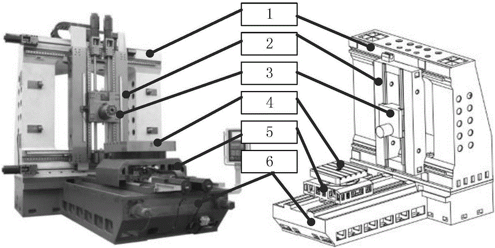
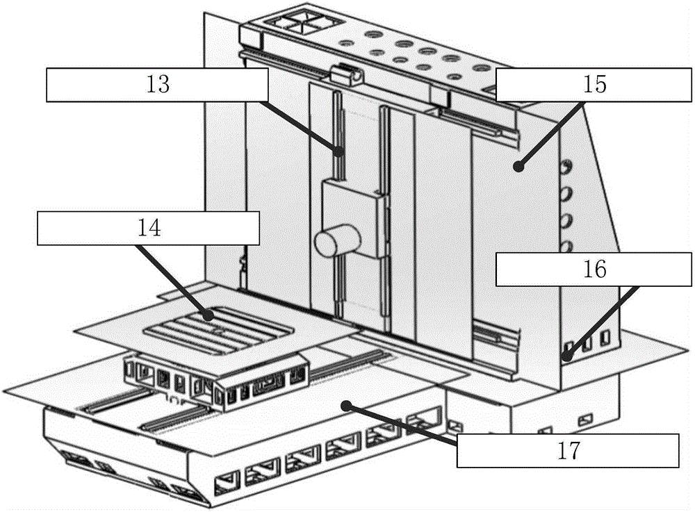
[0061] Taking the active design of the joint surface of the bed column of a certain type of precision coordinate boring machine as an example, the present invention will be described in detail with reference to the accompanying drawings.

[0062] 1. Ansys Workbench automatically analyzes and extracts processing space deformation

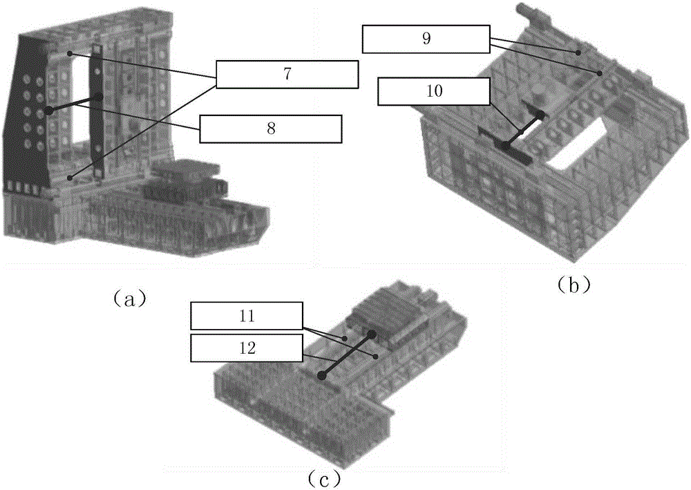
[0063] (1) Machine tool structure simplification

[0064] 1) Delete the fillet and chamfer of the small size (size <20mm) in the part;

[0065] 2) Delete small features such as mounting bolt holes, screw holes, and oil injection holes that do not affect the analysis and calculation;

[0066] 3) Simplification of the transmission system: the transmission mechanisms such as gears and worm gears inside the large frame structure are removed. In the analysis of the whole machine, only the outer casing, the main shaft and the transmission shaft are kept, and the quality characteristics of the original structure are equivalent by changing their material d...


PUM


Abstract

The invention discloses a machine tool assembling joint surface design method capable of taking deformation error compensation as a target. The method comprises the following steps: in CAD (Computer Aided Design) software, according to statics analysis requirements and the structural characteristics of a machine tool, carrying out structure simplification; then, carrying out parameterized assembling on a machine tool entity model; importing the entity model subjected to the simplification and the parameterized assembling into finite element analysis software Ansys Workbench; creating a container capable of carrying out automatic analysis and extraction deformation by utilizing the software, carrying out orthogonalization of a processing spatial position and mesh generation, and meanwhile, finishing statics analysis and result storage; then, through data learning, obtaining the practical deformation amount of a machine tool assembling nominal joint surface under a situation that whole processing space deformation is considered; flipping the obtained practical deformation amount, adding the flipped amount and the nominal joint surface to serve as an actively designed machine tool assembling joint surface; and on the basis of a Monte Carlo method and a least square method, finishing profile tolerance design of the assembling joint surface with the combination of a data regression technology.

Description

technical field [0001] The invention belongs to the field of mechanical manufacturing and design, and relates to a data learning-based method for designing a joint surface of a machine tool assembly, including Workbench automatic analysis and extraction deformation technology, joint surface active design technology and joint surface profile tolerance design technology, and specifically relates to a A design method for the joint surface of machine tool assembly aiming at offsetting the deformation error. Background technique [0002] Under the action of cutting force, clamping force, gravity and inertial force, CNC machine tools will produce obvious additional geometric deformation, thereby destroying the original mutual positional relationship of each component of the machine tool and generating additional processing errors, which is called deformation (force) error. Studies have pointed out that deformation errors account for 12% of all machine tool errors, and are the thi...

Claims


Application Information

Patent Timeline
IPC IPC(8): G06F17/50
CPCG06F30/17G06F30/23
Inventor 刘志刚洪军刘鹏郭俊康赵强强陈以磊荆冲周强
Owner XI AN JIAOTONG UNIV
Why Eureka
Try Eureka