A reactor for being directed at carbon containing fuel carries out entrained flow gasifica tion

A technology of a reactor and an entrained flow bed, applied in the field of reactors, can solve the problems of too little consideration for the replaceability of the slag discharge body, high corrosion of the slag discharge device, expensive heat treatment, etc., and achieves easy installation, low cost and reduced corrosion. Effect

Active Publication Date: 2016-10-05
CHOREN INDTECHN
View PDF8 Cites 4 Cited by
  • Summary
  • Abstract
  • Description
  • Claims
  • Application Information

AI Technical Summary

Problems solved by technology

[0012] However, a disadvantage of these known solutions is that too little consideration is given to the simple replaceability of the slag discharge body after a long operating time in the structural configuration of the intermediate floor
[0014] If a non-replaceable slag discharge device has to be replaced together with the support plate, then, for example, according to DE 10 2006 031 816 A1, DE 20 2008 009 249 U1 and DE 20 2010 015 889 U1, the known implementation of these support plates A disadvantage of this approach is that the support plates require a forged receiving ring which has to be welded into the mantelschuss of the pressurized reactor wall, and the reactor wall has to undergo a subsequent, expensive heat treatment
[0015] Another disadvantage related to the known structural configuration of the slag discharge area is that there are often unventilated cavities or dead spaces around the slag discharge regulator (Schlackeablauftrichter), from which aggressive gases and Moisture from the cooling chamber can pool in these cavities or dead spaces and cause rapid high corrosion and time consuming repairs at the slag discharge

Method used


Image

  • A reactor for being directed at carbon containing fuel carries out entrained flow gasifica tion
  • A reactor for being directed at carbon containing fuel carries out entrained flow gasifica tion
  • A reactor for being directed at carbon containing fuel carries out entrained flow gasifica tion

Examples


Embodiment Construction

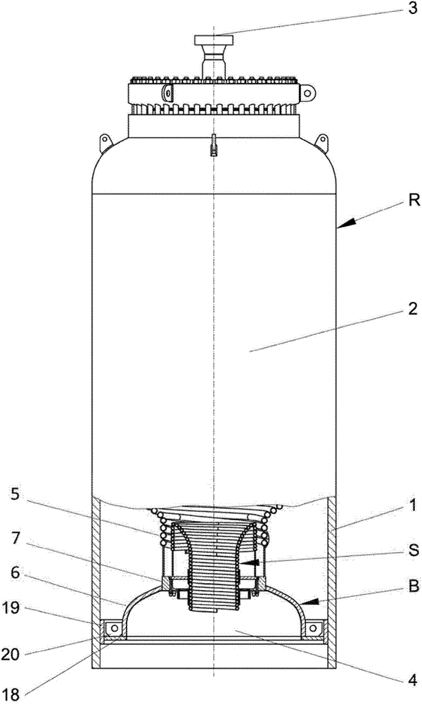
[0041] as from figure 1 It can be seen that the reactor R for the entrained-bed gasification of carbonaceous fuels, such as pulverized coal, at a temperature of 1200° C. to 1800° C. and a pressure of up to 80 bar basically consists of a reaction chamber 2 and a support A cooling chamber 4 connected to the reaction chamber inside the pressure reactor wall 1, wherein in the reaction chamber 2 there are arranged at least one burner 3 for partial oxidation of the fuel into crude synthesis gas and a burner for internal cooling with water. In the cooling screen 5 that limits the reaction space, and in the cooling chamber 4, the raw synthesis gas and the slag particles transported together are in contact with the cooling liquid and can be cooled below the ash melting point.

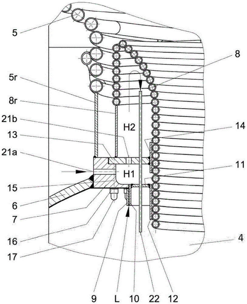
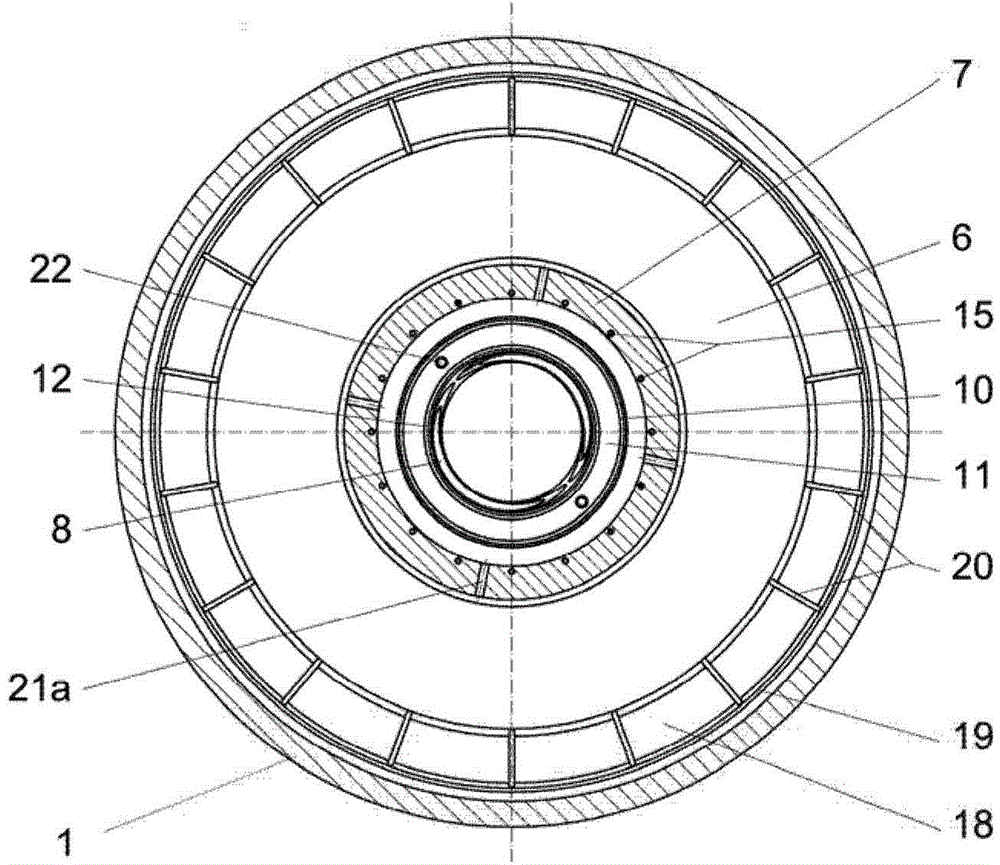
[0042] The two chambers are separated by a straight or arched intermediate floor B assembled from concentrically arranged annular elements and enclosing a central slag discharge body S, wherein the slag discharg...


PUM


Abstract

The invention relates to a reactor for being directed at carbon containing fuel carries out entrained flow gasifica tion, it has a reacting chamber and one cooling chamber that borders on this reacting chamber within the reaction wall of pressure -bearing. The invention aims at providing a corrosivity wearing and tearing that the structure solution of bottom plate in the middle of is used for, this solution improves effective operating duration of entrained flow gasifica tion ware, and its mode does, reduces in middle bottom plate region to also reduce consumeing of dismantlement of sediment eduction gear and installation under repair. This purpose is following the realization, a plurality of components of this centre bottom plate each other continuously the unoccupied place and discharge to personally experience sth. Part of the body with this sediment and be connected as going to the fields for discharge at this sediment and form a gas space's air seal, limited this cooling chamber of this centre bottom plate downside between the body and this reaction wall, and the cavity between these components of this centre bottom plate through the pressure balance passageway each other, sweep the device and be connected with the gas space of this cooling chamber with an inert gas.

Description

technical field [0001] The invention relates to a reactor for the entrained-bed gasification of carbonaceous fuels, the reactor having a reaction chamber and a cooling chamber connected to the reaction chamber within a pressurized reactor wall. Background technique [0002] This entrained bed gasification of carbonaceous fuels is used for the generation of hydrogen- and carbon-monoxide-rich gases, which are applied as synthesis gas, reducing gas, town gas or gas for energy purposes. [0003] During gas generation, the gasification of ash-like coal with the participation of oxygen and water vapor or carbon dioxide takes place as a flame reaction in a floating mist at a temperature of 1200° C. to 1800° C. and a pressure of up to 80 bar, wherein In addition to the desired crude gas, mineral residues of the molten liquid occur in the form of slag particles. The gasification method of the same principle applies to the gasification of liquid fuels (tars, residual oils), suspensio...

Claims


Application Information

Patent Timeline
Patent Type & Authority Applications(China)
IPC IPC(8): C10J3/48C10J3/74
CPCC10J3/485C10J3/76C10J3/78C10J2200/09C10J2300/0916
Inventor 法比安·艾佐尔德
Owner CHOREN INDTECHN
Why Eureka
Try Eureka